
User guide

- 7 -
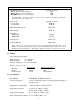
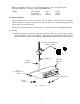
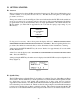
4) Select the ribbon cable end with the adjacent, heavy, black mass. Insert this end of the
ribbon cable into the DV-III Rheometer head. Insert the other end of the ribbon cable into
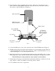
the connector on the DV-III base (see Figure 3).
100-240 VAC 50/60 HZ 220VA
MODEL DV-III BASE UNIT
240 CUSTHING ST.
STOUGHTON, MA USA 02072
APPROVED POUER SUPPLY
TUV RHEINLAND
LICENSE NO. R9051346
RECOGNIZED COM,PONENT
UL FILE NO. D 122103
NOTE
ANALOG OUTPUTS
ON SERIAL I/0
CONNECTOR
A.C. Power
Connector
A.C. Fuse
Power ON/OFF
Switch
RTD Temperature
Probe Connector
Ribbon Cable
Connector
RS-232 Serial
Printer/Computer
Analog Output(s)
Ribbon Cable
Connector
Figure 3
5) Connect the RTD probe to the socket on the back side of the DV-III Rheometer (Figure 3).
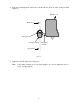
6) The Rheometer must be leveled before the instrument is zeroed and readings are taken. The level
is adjusted using the three leveling screws on the base. Adjust so that the bubble level on top
of the DV-III (Figures 1, 2) is centered within the circle.
7) Make sure that the AC power switch at the rear of the base unit is in the OFF position. Connect
the AC plug to the socket on the back of the DV-III base and plug it into the appropriate AC line.
The DV-III must be earth grounded to ensure against electronic failure!!
8) Temperature monitoring is assured (after the instrument has stabilized) to within ±1.0°C in the
range -100°C to +150°C and within 2°C in the range 150°C to 300°C.
9) For Cone/Plate models refer to Appendix A.
(s)
Rheometer Head