
Install Instructions

BALL BEARING INSERT INSTALLATION
SPHERICAL OD INSERTS - Place into housing load slot,
positioning the anti-rotation rivet in the load slot. Using a bar slipped
into the insert bore, swing insert into place within the housing. A
snug fit should result. If insert can swivel by hand, the housing fit
is too loose, replace entire unit. If heavy force is required, fit is
too tight
(Do not hammer
). - replace entire unit. Insure alignment
of the lube hole in outer race and the grease groove in housing
bore.
CYLINDRICAL OD INSERTS - Be sure housing bore is clean
and free of debris. Press the bearing into the housing by applying
force to the face of the outer ring
. Do not hammer on any
component of the bearing or apply force to inner ring
. For
recommended housing bore tolerance, consult BROWNING/EPT
Bearing Application Engineering.
BEARING INSTALLATION
1. CHECK AREA - Clean and organize bearing installation
area, and keep well lit. Be sure mounting surfaces are clean
and flat.
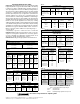
2. CHECK SHAFT - Shaft should be within tolerance range
shown in Table 1, clean, and free of nicks and burrs. Mount
bearing on unused section of shafting or repair/replace
shafting as required.
3. INSTALL UNIT - Slide the bearing unit and/or locking collar
on shaft. (If the projecting side of the bearing is to be mounted
toward the machine, put the locking collar on first.) If it is
difficult to mount the bearing on shaft, use a piece of emery
cloth to reduce any high spots on shaft.
Do not hammer on
any component of the bearing
4. CENTER INSERT - The expansion unit must be centered
in the housing to allow axial shaft expansion. Move the
bearing as far as it will go in both directions in the housing
and determine the centered position. It may be necessary to
unload the bearing while moving the assembly.
© Emerson Power Transmission Manufacturing, L.P. or affiliates 2006. All rights reserved.
WARNING
!
High voltage and rotating parts may cause
serious or fatal injury.
Turn off power to install or service.
Operate with guards in place.
Read and follow all instructions.
BALL AND ROLLER BEARINGS
INSTALLATION INSTRUCTIONS
PN 786515
PS-740-0001
Rev 01
December 2006
F O R M
™
These instructions cover setscrew and eccentric locking ball and roller bearings. It is important that they be read in their entirety before
attempting installation or removal. The procedures indicated should be carefully followed. Failure to do so can result in mis-installation,
which could cause bearing performance problems as well as serious personal injury.
5. FASTEN UNIT IN PLACE - Install housing attachment bolts,
check and align bearing and tighten attachment bolts. Rotate
shaft slowly to center bearing.
5.1 SET SCREW INSERTS
a. Setscrews in a multiple bearing setup should be
aligned.
b. Torque first set screw to one half recommended
torque. Torque second set screw to full torque. Torque
first set screw to full torque. Review Table 2 for Ball
Bearings and Tables 3 and 4 for Roller Bearings set
screw torque.
c. Check shaft again for freedom of rotation.
5.2 ECCENTRIC LOCK INSERTS
a. Rotate locking collar in the direction of shaft rotation
until hand tight. Lock tightly with a drift pin and
hammer or spanner wrench and hammer. Tighten
setscrews to torque specified in Table 5.
b. Check shaft again for freedom of rotation.
5.3 BOA CONCENTRIC INSERTS
a. Be sure that BOA concentric collar is fitted square
and snug against the shoulder on the inner ring.
b. Torque BOA concentric collar cap screw to torque
recommended in Table 6.
6. CHECK HOUSING ALIGNMENT - The maximum
permissible static misalignment of the shaft is 2° for ball
bearings, 1.5° for roller bearings, except for 900 and 920
series tapered roller bearings. The 900 and 920 series have
no misalignment capabilities.
7. INSTALL 2nd UNIT - Repeat Steps 4 through 6 for each
additional bearing used on the shaft
Emerson Power Transmission
909 N. Lafayette Street
VALPARAISO, IN 46383
Phone: 219-465-2211
www.emerson-ept.com