Safe Operation Practices • Set-Up • Operation • Maintenance • Service • Troubleshooting • Warranty Operator’s Manual Self Propelled Mower — Model Series A00, A10, A20, and B20 WARNING READ AND FOLLOW ALL SAFETY RULES AND INSTRUCTIONS IN THIS MANUAL BEFORE ATTEMPTING TO OPERATE THIS MACHINE. FAILURE TO COMPLY WITH THESE INSTRUCTIONS MAY RESULT IN PERSONAL INJURY. MTD LLC, P.O. BOX 361131 CLEVELAND, OHIO 44136-0019 Printed In USA Form No.
1 To The Owner Thank You Thank you for purchasing a Lawn Mower manufactured by MTD. It was carefully engineered to provide excellent performance when properly operated and maintained. If applicable, the power testing information used to establish the power rating of the engine equipped on this machine can be found at www.opei.org or the engine manufacturer’s web site. Please read this entire manual prior to operating the equipment.
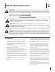
Important Safe Operation Practices 2 WARNING: This symbol points out important safety instructions which, if not followed, could endanger the personal safety and/or property of yourself and others. Read and follow all instructions in this manual before attempting to operate this machine. Failure to comply with these instructions may result in personal injury. When you see this symbol.
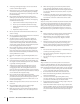
12. A missing or damaged discharge cover can cause blade contact or thrown object injuries. 13. Many injuries occur as a result of the mower being pulled over the foot during a fall caused by slipping or tripping. Do not hold on to the mower if you are falling; release the handle immediately. 14. a. Step back from mower to fully extend your arms. b. Be sure you are well balanced with sure footing. c. Pull the mower back slowly, no more than half way toward you. d. Repeat these steps as needed.
Service 3. Check the blade and engine mounting bolts at frequent intervals for proper tightness. Also, visually inspect blade for damage (e.g., bent, cracked, worn) Replace blade with the original equipment manufacture’s (O.E.M.) blade only, listed in this manual. “Use of parts which do not meet the original equipment specifications may lead to improper performance and compromise safety!” 4. Mower blades are sharp and can cut. Wrap the blade or wear gloves, and use extra caution when servicing them.
Notice Regarding Emissions Engines which are certified to comply with California and federal EPA emission regulations for SORE (Small Off Road Equipment) are certified to operate on regular unleaded gasoline, and may include the following emission control systems: Engine Modification (EM), Oxidizing Catalyst (OC), Secondary Air Injection (SAI) and Three Way Catalyst (TWC) if so equipped.
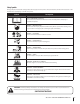
Safety Symbols This page depicts and describes safety symbols that may appear on this product. Read, understand, and follow all instructions on the machine before attempting to assemble and operate. Symbol Description READ THE OPERATOR’S MANUAL(S) Read, understand, and follow all instructions in the manual(s) before attempting to assemble and operate DANGER — ROTATING BLADES To reduce the risk of injury, keep hands and feet away.
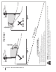
Section 2 — Important Safe Operation Practices Figure 1 line Figure 2 (TOO STEEP) 15° Slope WARNING! Slopes are a major factor related to tip-over and roll-over accidents which can result in severe injury or death. Do not operate machine on slopes in excess of 15 degrees. All slopes require extra caution. Always mow across the face of slopes, never up and down slopes. To check the slope, proceed as follows: 1. Remove this page and fold along the dashed line. 2.
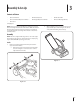
3 Assembly & Set-Up Contents of Carton • One Lawn Mower • • One Lawn Mower Operator’s Manual • • One Fuse† One Grass Catcher† • One Bottle of Oil One Engine Operator’s Manual • One Side Discharge Chute† † If Equipped NOTE: Please be aware that this Operator’s Manual covers both the low and high wheel models of this mower. While this manual illustrates the low wheel model, the instructions and features are equally applicable to the high wheel model as well, unless otherwise noted. b.
2. Remove the T-bolts from the handle brackets as shown in Figure 3-3. C C Figure 3-5 4. Figure 3-3 3. Follow the steps below to complete handle assembly: a. The rope guide is attached to the right side of the upper handle. Loosen the wing knob which secures the rope guide. See Figure 3-6. Pull upward on the handle until holes in lower handle (shown in Figure 3-3 deck cutaway) line up with holes in handle bracket. See Figure 3-4. A D B A B B C Figure 3-6 a.
b. Slip plastic channel of grass bag over hooks on the frame. See Figure 3-7. B Side Discharge Chute (If Equipped) Your mower may be shipped as a mulcher. To convert to side discharge, make sure grass catcher is off of the unit and rear discharge door is closed. 1. On the side of the mower, lift the side mulching plug. See Figure 3-9. Side Mulching Plug 1 A 2 Figure 3-7 2. Follow steps below to attach grass catcher: a. Lift rear discharge door. b.
Adjustments IMPORTANT: Both the front and rear wheels must be placed in the same relative position. For rough or uneven lawns, move the height adjustment levers to a higher position. This will stop scalping of grass. Cutting Height There is a cutting height adjustment lever located above the front and rear right wheel. Handle Pitch (If Equipped) 1. Pull the height adjustment lever towards wheel (unit will tend to fall when lever is moved outward).
4 Controls and Features Blade Control Drive Control Recoil Starter Primer † Grass Catcher † Cutting Height Adjustment Lever Side Discharge Chute † Cutting Height Adjustment Lever Mulch Plug † † If Equipped Blade Control Figure 4-1 The blade control is attached to the upper handle of the mower. Depress and squeeze it against the upper handle to operate the unit. Release it to stop engine and blade. WARNING: This blade control is a safety device. Never attempt to bypass its operations.
5 Operation Starting & Stopping Engine Using Grass Catcher (If Equipped) Refer to the Engine Operator’s manual packed with your lawn mower for instructions on starting and stopping the engine. You can use the grass catcher to collect clippings while you are operating the mower. Using Your Lawn Mower 1. Attach grass catcher following instructions in the “Assembly & Set-Up” section. Grass clippings will automatically collect in bag as you run mower. Operate mower till grass bag is full. 2.
6 Maintenance & Adjustments Maintenance 2. General Recommendations The transmission is pre-lubricated and sealed at the factory and does not require lubrication. 3. Follow the accompanying engine manual for lubrication schedule and instruction for engine lubrication. • Always observe safety rules when performing any maintenance. • The warranty on this lawn mower does not cover items that have been subjected to operator abuse or negligence.
Deck Wash (If Equipped) Engine Care Your mower’s deck may be equipped with a water port on its surface as part of its deck wash system. A list of key engine maintenance jobs required for good performance by the mower is given below. Follow the accompanying engine manual for a detailed list and instructions. Use the deck wash to rinse grass clippings from the deck’s underside and prevent the buildup of corrosive chemicals. Complete the following steps AFTER EACH MOWING: 1.
7 Service Blade Care 4. WARNING: When removing the cutting blade for sharpening or replacement, protect your hands with a pair of heavy gloves or use a heavy rag to hold the blade. Remove blade from the adapter for testing balance. Balance the blade on a round shaft screwdriver to check. Remove metal from the heavy side until it balances evenly. When sharpening the blade, follow the original angle of grind. Grind each cutting edge equally to keep the blade balanced.
Replacing Battery (If Equipped) Charging Battery (If Equipped) WARNING: Batteries contain sulfuric acid which may cause burns. Do not short circuit or mutilate batteries in any way. Do not put batteries in fire as these may burst or release toxic materials. 1. Unhinge cover seal and lift off battery cover. 2. Remove positive and negative leads from battery, and pull up on battery to remove. See Figure 7-2.
Replacing Fuse (If Equipped) Off-Season Storage The electric starter circuit and battery are protected by a 40 ampere fuse. If the fuse burns out, the electric starter will not operate. If the unit fails to start with the electric starter, perform the following steps to check the fuse inside the battery housing: The following steps should be taken to prepare your lawn mower for storage. • 1. Open the battery cover as described in Replacing Battery.
8 Troubleshooting Problem Engine Fails to start Cause Remedy 1. Blade control disengaged. 1. Engage blade control. 2. Spark plug boot disconnected. 2. Connect wire to spark boot. 3. Fuel tank empty or stale fuel. 3. Fill tank with clean, fresh gasoline. 4. Engine not primed (if equipped with primer). 4. Prime engine as instructed in the Operation section. 5. Faulty spark plug. 5. Clean, adjust gap, or replace. 6. Blocked fuel line. 6. Clean fuel line. 7. Engine flooded. 7.
Problem Uneven cut Mower will not self propel Cause Remedy 1. Wheels not positioned correctly. 1. Place front and rear wheels in same height position. 2. Dull blade. 2. Sharpen or replace blade. 1. Belt not installed properly. 1. Check belt for proper pulley installation and movement. 2. Debris clogging drive operation. 2. Stop engine, disconnect spark plug boot, and clean out debris. 3. Damaged or worn belt. 3. Inspect and replace belt.
9 Replacement Parts Component Part Number and Description 759-3336 BS-591868 951-14437 98079-56846 Spark Plug (Briggs & Stratton E/EX Series Models) Spark Plug (Briggs & Stratton Quantum Models) Spark Plug (MTD) Spark Plug (NGK BPR6ES) (Honda) BS-298090S† Fuel Filter (Briggs & Stratton) 951-10358A Fuel Filter (MTD) 16952-ZA8-800 Fuel Filter (Honda) BS-799579 BS-798452 951-10298 Air Filter (Briggs & Stratton - Foam) Air Filter (Briggs & Stratton - Pleated) Air Cleaner Kit (MTD) BS-491588S BS-493537S† 1
Component Part Number and Description 731-07486† Discharge Chute 942-0741A 942-0741-X Mulching Blade Xtreme Mulching Blade 764-04077B† 964-04116B† Grass Bag (Black) Grass Bag (Yardman) 954-04259A Belt 725-06121† Battery Charger 725-04903† Battery 731-09728† Push Key † If Equipped ‡ Not Shown Phone (800) 800-7310 or (330) 220-4683 to order replacement parts or a complete Parts Manual (have your full model number and serial number ready).
10 Attachments & Accessories Component Model Number and Description 490-850-0005 Blade Removal Tool — Holds blade in place for faster, safer removal. SPW-134 Spark Plug Wrench — Duel ended wrench to serve multiple uses. Fits ¾” or 13⁄16” hex plug. 490-850-0008 Oil Siphon — Makes it easy to transfer gas, oil and liquids from tank to container. 490-850-0016 Side Discharge Blower — Blows leaves, grass clippings and debris. Eliminates need for separate blower. Easy installation with no tools.
Component Model Number and Description 22216 STA-BIL® fuel Stabilizer, 32 oz — Treats 80 gallons of fuel. Keeps stored fuel fresh for quick, easy starts. Prevents corrosion from moisture and ethanol-induced attraction. Prevents gum and varnish. 490-290-0012 Mower Cover — Protects your mower against sun, rain and dust damage. Coated for maximum water resistance and repellency. U.V. and milddew resistant 490-900-0062 Non-Stick Mower Deck Spray — Long-Lasting anti-stick graphite spray.
MANUFACTURER’S LIMITED WARRANTY FOR The limited warranty set forth below is given by MTD LLC with respect to new merchandise purchased and used in the United States and/or its territories and possessions, and by MTD Products Limited with respect to new merchandise purchased and used in Canada and/or its territories and possessions (either entity respectively, “MTD”). b. Log splitter pumps, valves, and cylinders have a separate one- year warranty. c.
Medidas importantes de seguridad • Configuración • Funcionamiento • Mantenimiento • Servicio • Solución de problemas • Garantía Manual del operador Podadora tipo abonadora autopropulsada — Modelo Serie A00, A10, A20, Y B20 ADVERTENCIA LEA Y SIGA TODAS LAS INSTRUCCIONES DE ESTE MANUAL ANTES DE PONER EN FUNCIONAMIENTO ESTA MÁQUINA. SI NO RESPETA ESTAS INSTRUCCIONES PUEDE PROVOCAR LESIONES PERSONALES. MTD LLC, P.O. BOX 361131 CLEVELAND, OHIO 44136-0019 Impreso en Estados Unidos de América Formulario No.
Al propietario Gracias Gracias por comprar una máquina podadora fabricada por MTD. La misma ha sido diseñada cuidadosamente para brindar excelente rendimiento si se la opera y mantiene correctamente. Por favor lea todo este manual antes de operar el equipo. Le indica cómo configurar, operar y mantener la máquina con seguridad y fácilmente.
2 Medidas importantes de seguridad ADVERTENCIA: La presencia de este símbolo indica que se trata de instrucciones importantes de seguridad que se deben respetar para evitar poner en peligro su seguridad personal y/o material y la de otras personas. Lea y siga todas las instrucciones de este manual antes de poner en funcionamiento esta máquina. Si no respeta estas instrucciones puede provocar lesiones personales.
8. No ponga las manos o los pies cerca de las piezas rotatorias o en la tolva de la cortadora. El contacto con las cuchillas puede producir la amputación de manos y pies. 9. Una cubierta de descarga faltante o dañada puede provocar el contacto con la cuchilla o lesiones por objetos arrojados. 10. Muchas lesiones ocurren como resultado de pasar la cortadora sobre los pies durante una caída provocada por derrapes o tropiezos.
Niños Pueden ocurrir accidentes trágicos si el operador no está atento a la presencia de niños. Por lo general a los niños les atraen las podadoras y la actividad de podar el césped. No entienden los riesgos ni los peligros. Nunca dé por sentado que los niños permanecerán en el mismo lugar donde los vio por última vez. 1. Mantenga a los niños fuera del área de trabajo y bajo estricta vigilancia de un adulto responsable además del operador. 2. Esté alerta y apague la podadora si un niño ingresa al área.
6 8. Nunca trate de ajustar una rueda o la altura de corte mientras el motor está en marcha. No modifique el motor 9. Los componentes de la tolva para recorte, cubierta de descarga y escudo de riel, están sujetos a desgaste y daños que podría dejar expuestas partes que se mueven o permitir que se arrojen objetos. Para proteger su seguridad, verifique frecuentemente todos los componentes y reemplácelos sólo con partes de los fabricantes de equipos originales (O.E.M.) listadas en este manual.
Símbolos De Seguridad Esta página representa y describe la seguridad los símbolos que pueden parecer en este producto. Lea, comprenda, y siga todas instrucciones de la máquina antes de intentar ensamblar y operar. Símbolo Descripción LEA EL MANUAL(S) DEL OPERADOR Lea, comprenda, y siga todas instrucciones en el manual (manuales) antes de operar el producto. PELIGRO— GIRANDO HOJAS Para reducir el riesgo de herida, guarde manos y pies lejos.
8 Sección 2 — Medidas importantes de seguridad Figura 1 tinua iscon nea d 15° lí 15° Pendiente ADVERTENCIA! Las pendientes son un factor importante relacionado con un vuelco y renovación de los accidentes que pueden provocar lesiones graves o la muerte. No utilice la máquina en pendientes de más de 15 grados. Todos pendientes requiere mayor precaución. Si no puede retroceder en la pendiente o si se siente inseguro en ella, no la recorte. Siempre corte el césped en toda la superficie de la cuesta.
3 Montaje y Configuración Contenido de la caja • Una Podadora • Uno Colector de Césped† • Uno Botella del Aceite • Uno Manual de Operador • Uno Manual de Operador de Motor • Uno Canal de Descarga Lateral† • Uno Fusible† †De ser equipado NOTA: Tenga en cuenta que este manual del operador abarca tanto los modelos de rueda alta y baja de este cortacésped.
2. Retire la T-pernos de la manija entre corchetes como se muestra en Figura 3-3. c. Vuelva a colocar tuercas y pernos de transporte retirarse antes en una reducción de los agujeros de la manija como se muestra en Figura 3-5. C C Figura 3-3 3. Siga los siguientes pasos para completar conjunto del mango: a. Tire hacia arriba en el asa hasta agujeros en la manija (que se muestra en Figura 3-3 corte de la cubierta) se alinean con los agujeros en el mango soporte. Vea Figura 3-4. Figura 3-5 4.
Colector de Césped (De ser equipado) 1. Para ensamblar el colector de césped (de ser necesario), Haga el cierto bolso es dio vuelta a la derecha el lado antes de reunir (la advertencia de la etiqueta será por fuera). a. Coloque la bolsa sobre el marco con el lado negro de plástico en el fondo. b. Deslice el canal de plástico sobre los ganchos del marco. Vea Figura 3-7. Para quitar al receptor de hierba, levante la puerta de descarga trasera en el cortacésped.
Ajustes IMPORTANTE: Tanto las ruedas delanteras y traseras deben colocarse en la misma posición relativa. Cuando el terreno es agreste o irregular cambie la palanca de ajuste de la altura a una posición más alta. De esta manera se cuida más el césped. Altura de Corte Hay una palanca de ajuste de altura de corte, situado encima de la rueda delantera derecha y trasera.. 1. Presione la palanca hacia la rueda (unidad tenderá a caer cuando se suelta la palanca). 2.
4 Controles Y Características Control de la transmisión Control de cuchilla Arrancador de retroceso Cebador † Colector de Césped † Palanca de ajuste de altura de corte Canal de Descarga Lateral † Clavija para abono † † De ser equipado Palanca de ajuste de altura de corte Figura 4-1 Control de Cuchilla Clavija Para Abono (De ser equipado) El control de la cuchilla está unido a la manija superior. Presione la manija de control de la cuchilla contra la manija superior para operar la unidad.
5 Funcionamiento Arranque y Parada del Motor Uso del Colector de Césped (De Ser Equipado) Consulte el manual del motor incluido con su podadora para obtener instrucciones sobre cómo iniciar y parar el motor. Puede utilizar el colector de césped para recoger dichos recortes mientras opera la podadora. Uso de la Podadora de Césped 1. Acople el colector de césped siguiendo las instrucciones en la sección de Montaje y Configuración.
6 Mantenimiento Y Ajustes Mantenimiento 2. Recomendaciones Generales La transmisión estado prelubricada y sellada en la fábrica y no requiere lubricación. 3. Siga el manual adjunto del motor para conocer las instrucciones y el programa de lubricación del mismo. • Respete siempre las reglas de seguridad cuando realice tareas de mantenimiento. • La garantía de esta podadora no cubre elementos que han estado sujetos al mal uso o la negligencia del operador.
Lavado de la Plataforma (De ser equipado) Cuidados para el motor La plataforma de su podadora está equipada con un puerto de agua sobre su superficie como parte del sistema de lavado de la plataforma. A continuación se presenta una lista de tareas de mantenimiento necesarias para el buen funcionamiento de la cortadora de césped. Siga el manual adjunto del motor para consultar la lista detallada y las instrucciones.
7 Servicio Cuidado de la Cuchilla 4. ADVERTENCIA: Cuando saque la cuchilla de corte para afilarla o reemplazarla, protéjase las manos usando un par de guantes para trabajo rudo o un trapo grueso para sostener la cuchilla. Inspeccione periódicamente el adaptador de la cuchilla en busca de rajaduras, especialmente cuando golpee un objeto extraño. Realice los reemplazos que resulten necesarios. Siga los pasos que aparecen debajo para realizar el mantenimiento de la cuchilla. 1.
Reemplazo de la batería (De ser equipado) Carga de la batería (De ser equipado) ADVERTENCIA: Las baterías contienen ácido sulfúrico que puede causar quemaduras. No ponga en corto circuito o mutile las baterías de ninguna manera. No coloque las baterías sobre fuego dado que pueden explotar o despedir materiales tóxicos. 1. Desbaratar junta de la tapa y levante tapa de la batería. 2. Retire los conductores positivo y negativo de la batería, y tire de la batería para extraerla. Vea Figura 7-2.
Reemplazo del fusible (De ser equipado) Almacenamiento Fuera de Temporada El circuito del arrancador eléctrico y la batería están protegidos por un fusible de 40 amperes. Si el fusible se quema, el arrancador eléctrico no funcionará. Si la unidad no se enciende con el arrancador eléctrico, siga los siguientes pasos para verificar que el fusible está dentro del alojamiento de la batería: Se deben seguir estos pasos para la preparación de la podadora para su almacenamiento. 1.
8 Solución de problemas Problema El motor no arranca Remedio 1. El control de lámina se retiró. 1. Contratar el control de lámina. 2. Alambre de bujía desconectado. 2. Unir el alambre a la bujía. 3. Depósito de combustible combustible vacío o añejo. 3. Llenar el tanque de la gasolina limpia, fresca. 4. ESTÁRTER no activado. (De ser equipado) 4. Ahogue el motor (ver la sección de Funcionamiento). 5. Bujía defectuosa. 5. Limpio, ajuste el hueco, o sustituir. 6. Línea de combustible bloqueada. 6.
Problema Demasiada vibración La podadora no abona el césped Corte desigual La podadora no avanza por sí misma Causa Remedio 1. Cuchilla floja o desequilibrada. 1. Apriete la cuchilla y el adaptador. Equilibre la cuchilla. 2. Cuchilla abollada. 2. Consulte a un distribuidor autorizado. 1. Césped húmedo. 1. No corte el césped cuando está mojado, espere hasta que sea más tarde para hacerlo. 2. Césped excesivamente alto. 2.
GARANTÍA LIMITADA DEL FABRICANTE La siguiente garantía limitada es otorgada por MTD LLC con respecto a nuevos productos adquiridos y utilizados en Estados Unidosy/o sus territorios y posesiones, y por MTD Products Limited con respecto a nuevos productos adquiridos y utilizados en Canadá y/o sus territorios y posesiones (cualquiera de las dos entidades, respectivamente, “MTD”). Esta garantía es adicional a la garantía de emisiones aplicables proporcionada con el producto.