Service Manual Model 3163 Contents Important Safety Information . . . . . . . . . . 1 No Spark at Burner . . . . . . . . . . . . 12-13 Specifications . . . . . . . . . . . . . . . . . . 2 Burner Ignites But Flame Will Not Hold . . 14-15 General Information . . . . . . . . . . . . . . 2 Trouble Shooting - Ventilation Fan . . . . 16-17 Direct Vent Requirements . . . . . . . . . . . 2 Diagnosing Cooling Problems . . . . . . . . . 18 Propane System . . . . . . . . . . . . . . . .
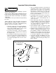
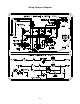
Important Safety Information • The use of improper rated fuses can lead to an electrical fire. In the event of a circuit overload, replace blown fuses with a fuse specified by Norcold. Fuse specifications are found in the "Specifications" section on page 2 of this manual. The correct fuse size is printed adjacent to the fuse on the refrigerator. WARNING Read this information before attempting to perform service on this refrigerator. Page 8 shows a wiring pictorial and diagram.
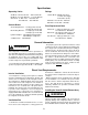
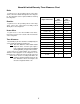
Specifications Ratings Operating Limits LP Gas Mode: 640 BTU/Hr. Input 11" W.C. Gas Supply .010" Orifice (LP10) AC Mode: 110 volts AC - 140 watts DC Mode: 12 volts DC - 140 watts AC Mode: 132 volts AC max. - 108 volts AC min. DC Mode: 15.4 volts DC max. - 11.5 volts DC min. Gas Mode: 11" W.C. max. - 10.5" W.C. min. 15.4 VDC max. - 10.5 VDC min. Current Draws Fuse Replacement Data AC Heating Element - 1.3 amp @ 110 volts AC 1.4 amps @ 120 volts AC DC Heating Element - 11.7 amps @ 12 volts DC 13.
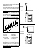
stitution will void the agencies’ certifications and the Norcold warranty. Refer to this manual for proper instructions. Install the refrigerator and vents as directed by Norcold without modification. Intake Pipe max. length 16" The clearance from the refrigerator’s left side (facing the front of the refrigerator) to the vehicle’s exterior wall is important. This is the area in which the inlet and outlet flexible piping will be connected to the vent terminal housing during installation.
Insulating the Flexible Exhaust Piping power cord to the receptacle. Place the "O" rings onto the ends of both flexible pipes. Bend the flexible pipes so they clear the top of the enclosure. Connect the piping as follows: The flexible exhaust pipe must be insulated prior to installation into the vent terminal housing. The flexible exhaust pipe connects to the flue tube of the refrigerator’s cooling unit and routes to the bottom opening of the vent terminal housing.
Check Out of Flame Failure Safety Device flame safety device will automatically close (an audible click will be heard as this device closes). 4. Turn the gas on at the manual shut-off valve. 5. Attempt to light the burner by placing the mode selection button to the gas mode. Do not push in the safety valve. 6. Without holding the safety valve in, the burner flame will not re-light. This indicates the flame failure safety device is functioning. 1.
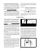
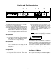
Lighting and Start-Up Instructions A B C E D G F Figure 8 The Lighting and Start-Up Instructions are located on the top portion of the interior door liner. Refer to Figure 8 for location of the operating controls. Notice: When warm humid weather conditions are observed, operate the refrigerator on either AC or DC electric for a minimum of five (5) minutes before attempting to follow the Start-Up Instructions for Gas operation. 3.
Norcold Limited Warranty Time Allowance Chart Rialta To gain access to the operating controls of the refrigerator, remove the drawer directly above the refrigerator. The interrupter can be replaced without removing the refrigerator. EuroVan To gain access to the operating controls of the refrigerator, remove the control panel assembly located directly above the refrigerator.
Wiring Pictorial & Diagram 8
Important Safety Information - AC Circuit Read this information before attempting to perform service on this refrigerator. Understand the service procedures before performing the service. WARNING Always apply the safety precautions on page 1 and the precautions listed below. Failure to follow these safety precautions can result in substantial property damage, severe personal injury, or death. • Use caution when performing the AC diagnostic procedures.
Refrigerator Will Not Operate on AC Is selector switch in the AC position? YES Is thermostat set at mid-range or higher? NO Is AC voltage at output of selector switch? YES Is AC voltage at input of selector switch? Is AC voltage to output of fuse? YES YES Is AC voltage at input of heater? (Black wires) NO Is AC voltage at input of fuse? NO Replace 3 amp fuse and start refrigerator. YES Is AC voltage at output of thermostat? YES Correct AC source to fuse.
Important Safety Information - DC Circuit Read this information before attempting to perform service on this refrigerator. Understand the service procedures before performing the service. WARNING Always apply the safety precautions on page 1 and the precautions listed below. Failure to follow these safety precautions can result in substantial property damage, severe personal injury, or death. • Use caution when performing the DC diagnostic procedures.
Refrigerator Will Not Operate on DC Electric Is selector switch set to DC? YES Is circuit breaker tripped or fuse blown? (DC to refrigerator) NO YES Set selector switch to DC and start refrigerator. Reset circuit breaker/replace fuse & start refrigerator. Replace DC heater. NO Are there loose wire connections? NO YES Is 12 VDC at output of selector switch? YES NO Repair loose connections and start refrigerator.
Important Safety Information - Gas Circuit Read this information before attempting to perform service on this refrigerator. Understand the service procedures before performing the service. WARNING Always apply the safety precautions on page 1 and the precautions listed below. Failure to follow these safety precautions can result in substantial property damage, severe personal injury, or death. • Propane gas can cause an explosion. Use caution when working with or near a propane gas system.
No Spark at Burner Is selector switch set to Gas? YES NO Is thermostat set to start? YES NO Set selector switch to Gas and start refrigerator. Set thermostat to start and light refrigerator. Install short jumper wire from relighter to within 1/8" of ground Remove spark electrode wire from relighter. Is circuit breaker tripped or fuse blown? (DC to refrigerator) NO Is 12 VDC present at terminal block? YES NO Reset breaker or replace fuse and start refrigerator.
Note: If flame is burning but the flame indicator lamp is not illuminated, check for 2 Volts DC from the relighter to the lamp. If 2 Volts DC is present, replace flame indicator lamp. If 2 Volts DC is not present, replace the relighter.
Burner Ignites But Flame Will Not Hold Is the DC voltage at terminal block between 10.5 - 15.4 VDC? YES NO YES Does flame hold? YES NO Correct DC voltage input. Remove white wires and jump interrupter terminals. Is the main gas supply on? Turn main gas supply on. YES NO Are white wires from relighter to interrupter secure & tight? YES Is refrigerator’s manual shut-off valve on? YES Is vent terminal housing free from obstructions? Is gas supply pressure at 10.5" - 11" W.C.
Important Safety Information - DC Fan Circuit Read this information before attempting to perform service on this refrigerator. Understand the service procedures before performing the service. WARNING Always apply the safety precautions on page 1 and the precautions listed below. Failure to follow these safety precautions can result in substantial property damage, severe personal injury, or death. • Propane gas can cause an explosion. Use caution when working with or near a propane gas system.
Trouble Shooting - Ventilation Fan Is the mode selection in the Gas position? NO YES Is 12 VDC present at input of 1 amp fuse? YES Is 12 VDC present at output of 1 amp fuse? NO Set mode selection switch to gas. Correct 12 VDC source to fuse. Disconnect red wire from fan to thermostat. Disconnect red wire from mode selection switch to thermostat. NO YES Is 12 VDC present at fan thermostat? Correct 12 VDC source to fan thermostat.
Diagnosing Cooling Problems Read this information before attempting to perform service on this refrigerator. Understand the service procedures before performing the service. See pictorial and trouble shooting guide on pages 17 & 18. 4. An off-level situation, if the infraction is marginal, will allow the refrigerator to continue to operate at a reduced level of cooling until the refrigerator is leveled. Greater off-level situations will stop the refrigerant circulation and cease cooling.
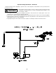
Refrigerator Removal Procedures WARNING U-Tube to Thermostat Improper removal and installation of the refrigerator can cause injury or property damage. Before attempting the procedures below, review the "Important Safety Information" on page 1 and the procedures below. Valve Shown in Off Position EuroVan Camper 1. Turn off the gas supply at the main tank. 2. Turn the refrigerator’s mode selector to "OFF". 3. Remove the vehicle’s middle bench seat. 4.
Rialta 11. Remove the phillips head screw and retaining washer which secure the vent-air exhaust and intake flexible vent piping to the vent terminal housing. See Figure 13. 12. Remove both the intake and exhaust vent piping from the vent terminal housing. Care must be taken not to damage the "O" ring seals when removing the piping. 13. Remove right dinette assembly cover panel to access the refrigerator retaining bracket. Reference "Right Dinette Assembly Cover Panel Removal" in the Interior Section. 14.
Vent Kit Assembly - 3163 No. Part No. Description 1 2 3 4 5 6 7 8 9 10 617980 617773 61761122 61633330 617923 617924 617922 617921 617920 617985 618007 618428 618429 618008 618030 618022 618023 O-Ring Washer Screw #8 - 15 x 1/2" S.S. Screw #8 - 32 x 5/16" Vent Terminal Housing Vent Terminal Gasket Back Plate Exhaust Disk Vent Cover Air Inlet Tube (EuroVan) Air Inlet Tube (Rialta) Air Exhaust Tube (EuroVan) Air Exhaust Tube (Rialta) Clamp 1.125 Clamp 1.
Final Assembly - 3163 23
Final Assembly - 3163 No. Part No.
Control Cover Assembly - 3163 No. Part No.
Control Assembly - 3163 No. Part No.
Burner Box Assembly - 3163 No. Part No.
!" ! ( #$% & & ' '