
Fan User Manual

14
Refer to Hot Gas Bypass line sizing tables for appropriate
size. Contact your Bryant representative for a copy of
these tables.
569J***D/E: Generally only one hot gas bypass system
will be applied on a two-circuit unit. Connect the hot gas
bypass system to Circuit 1 (first-on/last-off, connected to
the evaporator coil’s bottom circuit).
569J***D/E Piping Connections —
The 569J***D/E unit’s two circuits are designated Circuit 1
and Circuit 2. Circuit 1 is controlled by the thermostat’s Y1
(or TC1) contact and will be the first circuit on and last
circuit off. Circuit 2 is controlled by the thermostat’s Y2 (or
TC2) contact and this circuit is always the “lag” circuit.
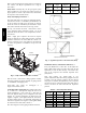
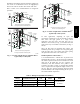
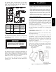
See Fig. 5 for location of Circuit 1 and Circuit 2 service
valves and field piping connections. Circuit 1 is on the
right-hand side of the service valve compartment; Circuit 2
is on the left.
When a single piece evaporator coil with two separate
circuits is connected to a 569J***D/E, the lower coil circuit
should be connected to the 569J***D/E unit’s Circuit 1 so
that the evaporator’s lower coil segment is first-on/last-off
(to avoid re-evaporation of condensate on dry lower coil
segments).
Circuit 1
Connections
Circuit 2
Connections
CKT
2
CKT
1
C10912
Fig. 5 -- 569J***D/E Service Valve Locations
Plan the Circuit 1 and Circuit 2 tubing segments carefully,
mark each segment and check constantly as piping systems
are assembled to avoid piping errors.
569J***D/E unit cannot be field-piped as a
single-circuit/tandem system.
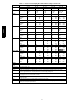
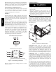
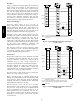
Connecting 524J to 569J***D/E: The 524J fan coil in sizes
12, 14 and 16 is a face-split coil design that also has its
circuits designated as 1 and 2. See Fig. 6. Note that the
lower coil segment changes as the arrangement of the 524J
changes. In a vertical arrangement, the 524J’s lower coil
segment is segment 2; this segment should be connected to
the 569J***D/E’s Circuit 1. In a horizontal arrangement, the
524J’s lower segment is now segment 1; this segment should
be connected to the 569J***D/E’s Circuit 1.
Note that refrigerant suction piping should be insulated.
524J
Arrangement
Cooling
Stage
524J Coil
Segment
Connect to
569J***D/E
Vertical
Y1
Y2
2
1
Circuit 1
Circuit 2
Horizontal
Y1
Y2
1
2
Circuit 1
Circuit 2
FIRST ON/LAST OFF = 2
VERTICAL INSTALLATION
FIRST ON/LAST OF F = 1
HORIZONTAL INSTALLATION
1
2
2
1
C10071
Fig. 6 -- Typical Evaporator Coil Connections (524J)
Install Filter Drier(s) and Moisture Indicator(s) —
Every unit MUST have a filter drier in the liquid line.
569J***D/E models require two filter driers (one in each
liquid line). Locate the filter drier(s) at the indoor unit,
close to the evaporator coil’s thermal expansion valve
(TXV) inlets.
569J units include one (569J***A/B) or two
(569J***D/E) Puron-duty filter drier(s), shipped in cartons
attached to the unit basepan. Remove the filter drier(s)
and prepare to install in the liquid line(s) at the evaporator
coil. Do not remove connection fitting plugs until ready to
connect and braze the filter drier into the liquid line
position.
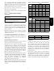
Table 8 – Puron-duty Filter Drier(s)
Model-Size Qty
Liquid
Line OD
Desiccant
Volume
Part
Number Ref
569J*07A/B 1
3
/
8
-in 8cu.in. KH43LG091
569J*08A/B 1
1
/
2
-in 16 cu. in. KH43LG085
569J*12A/B 1
1
/
2
-in 16 cu. in. KH43LG085
569J*14A/B 1
5
/
8
-in 16 cu. in. KH43LG086
569J*12D/E 2
3
/
8
-in 8cu.in. KH43LG091
569J*14D/E 2
1
/
2
-in 16 cu. in. KH43LG085
569J