
Fan User Manual

15
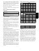
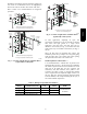
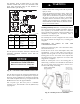
Installation of liquid line moisture indicating sightglass in
each circuit is recommended. Locate the sightglass(es)
between the outlet of the filter drier and the TXV inlet.
Refer to Table 9 for recommendations on refrigeration
specialties.
INDOOR
COIL CKT 2
AIRFLOW
INDOOR
COIL CKT 1
AIRFLOW
15 DIAMS
MIN
10
DIAMS
8 DIAMS
MIN
TXV
SENSING
BULB
EQUALIZER LINE
SIGHT GLASS
A LOCATION
SIGHT
GLASSES
B LOCATION
TXV
CKT 2
FILTER DRIER
A LOCATION
FILTER
DRIERS
B LOCATION
FLOW
TXV
SENSING
BULB
TXV
CKT 1
8 DIAMS
MIN
15 DIAMS
MIN
10
DIAMS
Single Circuit Coil Piping Configuration
For single compressor condensing units
Dual Circuit Coil Piping Configuration
For single compressor condensing units
15 DIAMS
MIN
10
DIAMS
8 DIAMS
MIN
INDOOR
COIL CKT
AIRFLOW
TXV
SENSING
BULB
EQUALIZER LINE
SIGHT GLASS
A LOCATION
TXV
FILTER DRIER
A LOCATION
LIQUID LINE
SOLENOID
VALVE
FLOW
LIQUID LINE
SOLENOID
VALVE
C10202
Fig. 7 -- Location of Sight Glass(es) and Filter Driers
Typical 569J***A/B Systems
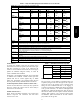
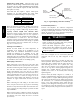
AIRFLOW
SUCTION
CIRCUIT 2
SUCTION
CIRCUIT 1
AIRFLOW
15 DIAMS
MIN
10
DIAMS
8 DIAMS
MIN
TXV
SENSING
BULB
EQUALIZER LINE
SIGHT
GLASSES
TXV
CKT 2
FILTER
DRIERS
LIQUID LINE
SOLENOID VALVE
CIRCUIT 2
FLOW
LIQUID LINE
SOLENOID VALVE
CIRCUIT 1
FLOW
TXV
SENSING
BULB
TXV
CKT 1
8 DIAMS
MIN
15 DIAMS
MIN
10
DIAMS
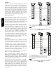
Dual Circuit Coil Piping Configuration
For two circuit condensing units
C10072
Fig. 8 -- Location of Sight Glasses and Filter Driers
Typical 569J***D/E Systems
In some applications, depending on space and
convenience requirements, it may be desirable to install 2
filter driers and sight glasses in a single circuit
application. One filter drier and sight glass may be
installed at A locations (see Fig. 7) or 2 filter driers and
sight glasses may be installed at B locations (see Figs. 7
and 8).
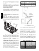
Select the filter drier for maximum unit capacity and
minimum pressure drop. Complete the refrigerant piping
from the indoor unit to the outdoor unit before opening
the liquid and suction lines at the outdoor unit.
Install Liquid Line Solenoid Valve —
It is recommended that a solenoid valve be placed in the
main liquid line (see Figs. 7 and 8) between the condensing
unit and the evaporator coil. Locate the solenoid valve at the
outlet end of the liquid line, near the evaporator coil
connections, with flow direction arrow pointed at the
evaporator coil. Refer to Table 9. (A liquid line solenoid
valve is required when the liquid line length exceeds 75 ft
[23 m].) This valve prevents refrigerant migration (which
causes oil dilution) to the compressor during the off cycle, at
low outdoor ambient temperatures.
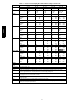
Table 9 – Refrigerant Specialties Part Numbers
LIQUID LINE
SIZE (in.)
LIQUID LINE
SOLENOID VALVE (LLSV)
LLSV
COIL
SIGHT
GLASS
FILTER
DRIER
3
/
8
EF680033 EF680037 KM680008
provided with unit
see Table 8
1
/
2
EF680035 EF680037 KM680004
5
/
8
EF680036 EF680037 KM680005
569J***D/E units require TWO sets of parts.
569J