
Thermostat User Manual


II. INSTALL THERMOSTAT
WARNING:
Before installing thermostat, turn off all
power to the unit. There may be more than one power
disconnect. Electrical shock can cause injury or death.
1. Turn off all power to unit.
2. If an existing thermostat is being replaced:
a. Remove existing thermostat from the wall.
b. Disconnect wires from existing thermostat. Do not
allow wires to fall back into the wall. As each wire
is disconnected, record wire color and terminal
connection.
c. Discard or recycle old thermostat.
NOTE: Mercury is a hazardous waste and must be disposed
of properly.
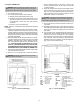
3. Remove the thermostat cover from wall plate (mount-
ing base) to expose mounting holes. See Fig. 1. With
the thermostat facing forward, press the back plate on
the left hand side top corner to release the two prongs
holding on the cover. Pull off the cover when the prongs
have been disengaged.
4. Route thermostat wires through large hole in mount-
ing base. Remove outer sheath from wires for added
flexibility. Standard solid or multi-conductor thermo-
stat wire should be used from the thermostat to the
unit. Size and length considerations are as fol-
lows: for a maximum distance from unit of 36 ft,
use 22AWG (American Wire Gage) wire; for a maxi-
mum distance from unit of 100 ft, use 18AWG wire.
5. Levelmountingbase against wall and mark wall through
the 2 mounting holes in base.
6. Drill two
3
⁄
16
-in. mounting holes in wall where marked.
WARNING:
Be careful not to drill into wiring in wall.
Electrical shock could result.
7. Secure mounting base to wall with 2 screws and
anchors provided. Ensure all wires exit through hole
in mounting base.
8. Adjust wire length and routing to allow proper closure
of the thermostat. Strip each wire at the end no more
than
1
⁄
4
-in. to prevent adjacent wires from shorting to-
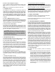
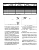
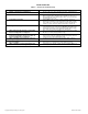
gether. Match and connect wires to terminals on the
thermostat. See Fig. 2-4 and Table 1.
CAUTION:
Improper wiring or installation may cause
damage to the thermostat. Check to ensure wiring is
correct before proceeding with installation of unit.
9. Push excess wiring into wall. Seal hole in wall to pre-
vent drafts.
10. Re-attach thermostat cover to back plate by aligning
the top two prongs of the back plate in the vertical groove
of the top cover and then snapping the cover onto the
back plate.
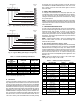
11. Turn on power to unit. The thermostat will receive power
from the unit. The thermostat will be powered by 24 v,
nominal (18 to 30 vac). Terminals R (+ 24 v), W1/O/B
(first stage heat or reversing valve), Y1 (first stage cool-
ing), and G (fan relay) will always be connected. Some
applications will use C (common),Y2 (second stage cool-
ing), or W2 (second stage heating).
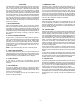
Fig. 1 — Thermostat Mounting
LEGEND
W2 — Second-Stage
Heat
Y2 — Second-Stage
Compressor
RS2 — Not Used
RS+5 — Not Used
RS1 — Not Used
RS
GND
— Not Used
W1/O/B — First-Stage Heat or
Reversing Valve
Y1 — First-Stage Compressor
G—Fan
W3/ECO — Third-Stage Heat or
Economizer (Not Used)
CK1 — Not Used
CK2 — Not Used
R—24 vac Transformer
C—24 vac Transformer
Common
Fig. 2 — Thermostat Wiring
—2—