
User guide


BRIDGED OPERATION (MONO mode)
When operated in BRIDGED (MONO) mode the two internal amplifier sections are operated
out of phase and the load is connected between the two HOT {RED binding post) terminals
with no connection to ground. The two amplifier sections operate together to form a single
push-pull amplifier with double the normal output voltage. In this mode the amplifier can
generate output voltages of greater than 50v(rms) into loads as low as 8 ohms thus producing
output power levels exceeding 400 watts (rms).
N.B. Only the left channel input is used in MONO mode.
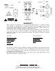
INPUT CONNECTORS
The 3B NRB is supplied with two pairs of input connectors: unbalanced RCA/phono and a
combination - 3 pin balanced XLR (pin 1 is ground, pin 2 is POSITIVE & pin 3 is NEGATIVB &
3 conductor balanced phone (TIP is positive, RING is negative & the sleeve is ground) -
jack with fully discrete active input circuitry. A toggle switch allows selecting between balanced
or unbalanced inputs. (The NPB has only the balanced XLRM" jacks).
All input connectors are gold plated and should be used only with quality gold plated input
cable connectors as a poorly plated connector will eventually corrode through the gold flash.
Bryston makes cables with appropriately heavily plated, high quality connectors, available
through your dealer.
OUTPUT CONNECTORS
The 3B is equipped with four binding post terminals (2 red, 2 black) which can accept either
standard banana plugs or bare wire. Refer to the rear panel hookup diagram and to the
descriptions of DUAL and MONO operation for details on how to connect speakers to these
terminals. Since the binding posts are gold-plated we recommend gold-plated banana plugs be
used for the lowest distortion.
N.B. Do not attempt to remove the red or black connector nuts from the binding post
connectors. They are not removable and attempting to force them off may break the
connector or strip the threads.
OUTPUT CABLES
For some time there have been available on the market special speaker cables constructed for
extra high current and low loss and distortion. These cables will cause no difficulty or instability
with any Bryston amplifier. In fact, we recommend that low inductance cables be used for the
smallest loss of signal between amplifier & speaker.
GROUNDING and the GROUND SWITCH
The left most switch on the rear panel is a GROUND LIFT switch. It is connected between the
chassis ground (including the third prong on the power line cord) and the signal ground. This
switch is normally left in the connected position n.. Occasionally a multi-amplifier rack
installation, or an unusual grounding situation with a preamp using a three wire power line
cord, will cause a ground loop between the signal ground and the chassis ground. This switch
will allow the elimination of the resulting hum in such cases without resorting to a "cheater"
plug by switching to the separated position 3Tl. Note that this switch does not disconnect the
chassis from the third prong on the power line cord which must be left intact for safety reasons.