GRINDERS Includes: MHG, FPG, FPG-2, LPG-2, G1, G2, G3, G2 trifecta™, G9, G9WD, G9-2 & G9-2T DBC SERVICE & REPAIR MANUAL BUNN-O-MATIC CORPORATION POST OFFICE BOX 3227 SPRINGFIELD, ILLINOIS 62708-3227 PHONE: (217) 529-6601 FAX: (217) 529-6644 To ensure you have the latest revision of the Operating Manual, or to view the Illustrated Parts Catalog, Programming Manual, or Service Manual, please visit the Bunn-O-Matic website, at www.bunn.com.
BUNN-O-MATIC COMMERCIAL PRODUCT WARRANTY Bunn-O-Matic Corp. (“BUNN”) warrants equipment manufactured by it as follows: 1) Airpots, thermal carafes, decanters, GPR servers, iced tea/coffee dispensers, MCP/MCA pod brewers thermal servers and Thermofresh servers (mechanical and digital)- 1 year parts and 1 year labor. 2) All other equipment - 2 years parts and 1 year labor plus added warranties as specified below: a) Electronic circuit and/or control boards - parts and labor for 3 years.
CONTENTS Warranty and Trademark..................................................................................................3 Introduction.....................................................................................................................4 Recommended Daily Cleaning.........................................................................................4 G9WD Packaging & Shim Removal.................................................................................5 Operating Controls...
INTRODUCTION The Grinder will store various amounts of whole bean coffee and grind it to a preset grind and amount into an awaiting funnel and filter or French Press from most commercial drip coffee brewers. The equipment is only for indoor use on a sturdy counter or shelf. Adequate space must be available above the grinder to raise the lid when adding beans. Use only with whole bean coffee.
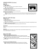
G9 WD - Packaging & Shim Removal WARNING MUST BE COMPLETED BY AUTHORIZED SERVICE PERSONNEL. DO NOT PLUG IN ! SEE INSTRUCTIONS BELOW BEFORE USING ! Step 1 - Remove & discard tape holding funnel arm in place. (Figure 1) Step 2 - Remove & discard two silicon tubes between funnel guide & housing. (Figure 2) Step 3 - Remove four screws in front housing panel. (Figure 3) Step 4 - Remove & discard shim under transducer. (Figure 4) Step 5 - Replace housing panel and secure four screws.
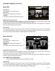
OPERATING CONTROLS Model G9WD d Grind Pad (a) Pressing initiates a grind cycle. Stop Pad (b) Pressing ends the operation of the grinder. e ® Pad (c) Pressing the copyright pad allows programming access. a Pads (d) “Hidden” buttons used to navigate setup and programming menus. Pads (e) Press button to select small, medium or large batch size. c b Model G9-2 Off/On/Start Switch OFF - (upper position) Switching to this position stops all operation of the grinder.
OPERATING CONTROLS (Continued) Model G9 Off/On/Start Switch OFF - (left position) Placing the switch in this position stops the operation of the grinder. ON - (center, resting position) The switch will return to this position after a grind cycle has begun and will remain in this position after grinding has ceased. START - (right, momentary position) Placing the switch in this position initiates a timed grind cycle.
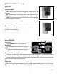
OPERATING CONTROLS (Continued) c Model MHG Grind Pad (a) Pressing initiates a timed grind cycle. Stop Pad (b) Pressing ends the operation of the grinder. ® PAD (c) Pressing the ® pad allows programming access. d d a b Hopper/Batch Selector Pads (d) These pads are located on the funnel depictions on each side of the grinder with a total of 6 pads. Selecting one of these pads will select the amount of grind and side from which to grind.
OPERATING CONTROLS (Continued) Model FPG Off/On/Start Switch OFF - (upper position) Switching to this position stops all operation of the grinder. ON - (middle position) The switch will return to this position after a grind cycle has begun and will remain in this position after grinding has ceased. START - (lower, momentary position) Pressing the switch to this position and releasing initiates a grind cycle.
TROUBLESHOOTING A troubleshooting guide is provided to suggest probable causes and remedies for the most likely problems encountered. If the problem remains after exhausting the troubleshooting steps, contact the Bunn-O-Matic Technical Service Department. • Inspection, testing, and repair of electrical equipment should be performed only by qualified service personnel. • All electronic components have ac voltage and dc voltage potential on their terminals.
TROUBLESHOOTING (cont.) Problem Probable Cause Remedy Grinder will not start. (Continued) 5. Motor Each motor is equipped with a temperature and current overload protection feature which will immediately shut off the motor when an overload has occurred. Check the grinder for obstructions. Refer to Service - Motor for testing procedures. 6. Relay Refer to Service - Relay for testing procedures. 7.
Problem Probable Cause Remedy Grinder starts, but will not dispense from hopper. 1. Hopper(s) Begin each grind cycle by visually inspecting the hopper(s) for ample supplies of whole bean coffee. 2. Blockage of hopper(s) Foreign materials must not block the openings at the bottom of the hopper(s). 3. Slide Gate Solenoids (Model LPG- Refer to Service - Solenoids for testing procedures. 2E only) 4. Timer Refer to Service - Timer for testing procedures. 5.
TROUBLESHOOTING (cont.) PROBLEM Incorrect coffee grind dispensed. PROBABLE CAUSE 1. Burr adjustment REMEDY Refer to the Adjustment section in the Installation and Operation Manual. Excessive chaff 1. Dechaffer Replace the dechaffer springs. Replacement dechaffer springs are provided in the literature package accompnting the grinder. Grinder only dispenses from one hopper 1. Hopper selector switch (Model LPG-2E only) Refer to Service - Hopper selector switch for testing procedures.
SERVICE This section provides procedures for testing and replacing various major components used in this grinder should service become necessary. Refer to Troubleshooting for assistance in determining the cause of any problem. WARNING - Inspection, testing, and repair of electrical equipment should be performed only by qualified service personnel. The grinder should be unplugged when servicing, except when electrical tests are required and the test procedure specifically states to plug-in the grinder.
SERVICE (Cont.) BAG SENSOR SWITCH (Models G1, G2, G3) or CUP SENSOR SWITCH (MODEL G2 TRIFECTA) 4. Disconnect the grinder from the power source. If voltage is present as described, proceed to #5. If voltage is not present as described, refer to the Wiring Diagrams and check the grinder wiring harness. 5. Check for continuity across the terminals on the bag sensor switch. If continuity is present as described, reconnect the wires, the switch is operating properly.
SERVICE (Cont.) 4. AC MOTOR AND GRIND CHAMBER 5. Check the voltage across the white, red or red/ black and white/blue wires on terminals L1 & L2 with a voltmeter. Connect the grinder to the power source. When the Off/On/Start switch is momentarily placed in the “START” (lower) position and then left in the “ON” (center) position and a bag is in place behind the coffee dispense chute. The indication must be: a. 120 volts ac for two wire 120 volt models. b. 230 volts ac for two wire 230 volt models c.
SERVICE (Cont.) AC MOTOR AND GRIND CHAMBER (cont.) 19. Install burr rotor cup (5). 20. Install grind selector dial plate and grind selector knob assembly on the grind chamber housing and secure with two .250”-20 screws. 21. Refer to Fig. 4 and reconnect the wires. 22. Refer to ADJUSTMENTS in the Installation and Operating Manual, and reset the burrs. 11. Clean all grinding burrs and mounting surfaces before reassembly. 12. Install the four .250”-20 cage nuts on the new motor. 13.
SERVICE (Cont.) AC MOTOR AND GRIND CHAMBER (cont.) 18 1 20 7 6 4 11 10 9 8 19 17 5 3 2 14 1 16 13 15 7 12 FIG. 5 GRIND CHAMBER COMPONENTS P1708 9. Remove bushing (10) and shaft extension (11) from grinder motor shaft. Inspect for wear. Replace if excessively worn or damaged. 10. Install shaft extension (11) and bushing (10) onto the grinder motor shaft. 11. Install stationary burr (9) inside the grind chamber and secure with two .250” -20 screws (8). 12.
SERVICE (Cont.) DC MOTOR AND GRIND CHAMBER - G1MD ONLY 4. 5. Check the voltage across the (+) and (-) terminals with a voltmeter. Connect the grinder to the power source. When the Off/On/Start switch is momentarily placed in the “START” (lower) position and then left in the “ON” (center) position and a bag is in place behind the coffee dispense chute. The indication must be approximately 108 volts dc. Disconnect the grinder from the power source. If voltage is present as described replace the motor.
SERVICE (Cont.) DC MOTOR AND GRIND CHAMBER - G1MD ONLY (cont.) BLU to BLU from Rectifier BLU to WHI/BLU from Relay (3) RED to Rectifier (-) BLK to Rectifier (+) 10. Remove motor and bracket out the rear of the grinder housing. 11. Remove the two .250”-20 screws securing the motor to the front of the mounting bracket. 12. Remove the two #10-32 screws securing the motor to rear of the mounting bracket. 13 Remove motor from bracket. 14. Clean all grinding burrs and mounting surfaces before reassembly.
SERVICE (Cont.) 14. Install the adjusting screw w/bearing (19) into the grind selector dial plate (18). 15. Install grind selector dial plate (18) with adjusting screw w/bearing (19) onto the grind chamber housing and secure with two .250”-20 screws (1). 16. Install grind selector knob (17) onto the grind selector dial plate (18). NOTE: Refer to ADJUSTMENTS and reset the burrs. DC MOTOR AND GRIND CHAMBER - G1MD ONLY (cont.) 11. Install burr (7) on burr auger rotor/spring assembly (6) securing with two .
SERVICE (Cont.) MOTOR (Models LPG & FPG) Removal and Replacement: 1. On Model LPG-2E, disconnect the black wire and the white wire to the motor from the main wiring harness, the red wire to the circuit breaker and the red wire to the Off/On/Start switch. On Model LPG disconnect the motor wiring harness from the main wiring harness. 2. On Model LPG-2E, disconnect the red wire from the left and right solenoid, the orange wire from the left solenoid and the violet wire from the right solenoid. 2 FIG.
SERVICE (Cont.) MOTOR (Models LPG & FPG) 8. Remove spacer plate (3) and set aside for reassembly. 9. Lift solenoid bracket and solenoids (4) over the motor and burr housing assembly (6) and set aside for reassembly. 10. Remove the #8-32 setscrew (5) and set aside for reassembly. 11. Lay motor on it’s side. 1 2 3 NOTE: Refer to Fig. 14 for the disassembly and assembly of the burrs and rotor. 4 2 12. Remove the two #10-32 fillister head screw securing burr housing cap (10) to the burr housing. 13.
SERVICE (Cont.) MOTOR (Models LPG & FPG) 13 MODEL LPG ONLY 10 11 12 13 14 15 16 17 18 FIG. 12 ROTOR/AUGER, BURRS AND MOTOR COVER P1051 NOTE: Steps 30 thru 33 apply only to Model LPG-2E. 30. Install solenoids and solenoid bracket (4) as an assembly on the new motor. 31. Install spacer plate (3) making sure the hole in the spacer plate aligns with the hole in the mounting ring. 32. Install solenoid plunger with spring and slide plate (2) as an assembly into the solenoid coil.
SERVICE (Cont.) DECHAFFER (Models LPG & FPG) 2 1 3 2 1 FIG. 13 DECHAFFER P1062 Location: The dechaffer spring plates are located in the burr housing cap. OPTONAL EXTRA FINE DECHAFFER P1063 FIG. 14 DECHAFFER REMOVAL/REPLACEMENT Removal and Replacement: Refer to Fig. 14 1. Remove coffee beans from hopper(s). 2. Lay grinder on it’s back. 3. Remove the #4-40 truss head screw securing dechaffer support (1) to the burr housing cap. 4. Remove dechaffer support (1). 5.
SERVICE (Cont.) 2. MOTOR (Models G9, G9-2, MHG) 3. 4. 5. 6. 7. 8. 9. FIG. 15 MOTOR P1309 10. Location: The motor is located in the upper wrapper under the hopper. 11. Test Procedure: 1. Remove the hole plug located on the right side of the housing. Press the red “Reset” button visible through the opening. Listen carefully for a “click”. This resets the motor protection circuit and may indicate that something other than coffee was inserted into the hopper for grinding. 12. 13.
SERVICE (Cont.) MOTOR (Models G9, G9-2, MHG) 9 8 7 6 5 4 3 2 1 1 2 0 15 14 13 12 11 3 4 5 1. 2. 3. 4. 5. FIG. 17 MOTOR AND GRIND CHAMBER 6. Rotor Indicator Adjustment Cap & Decal 7. Spring Adjusting Screw 8. Burr (Rotating) Burr Housing Cap 9. Burr (Stationary) Rotor Cup Shear Plate 10 6 7 8 9 P1311 4. Inspect the grind chamber and remove any foreign materials. The burrs will not properly seat in the chamber if any material or coffee particles remain. 5.
SERVICE (Cont.) SNUBBER (Models G9, G9-2, MHG) BLY E FIN EMPT UG THORO F T O H R IS E C R OV EA E S S R. EM SE AR CO WHI/ BLU to Snubber WHI/BLU to Relay WHI/BLK to Cordset (120V models) RED/BLK to Cordset (230V models) E NG COVRI BE NOTI Y EM E H HL OPPER BEFORE RAMB YC LEAN GRIND CH WHI/BLK to Snubber GRN to Chasis Ground YEL to Snubber P611 FIG. 18 SNUBBER FRANKLIN MOTOR Location: The snubber is located at the back of the motor attached to the right side of the wiring harness.
SERVICE (Cont.) Grinder Scale (Model G9WD only) CALIBRATION 1. Place empty funnel into funnel rails. 2. Press and hold the right hidden (copyright) button until the “MACHINE TYPE” menu appears. (See level 2 programming) 3. Press the middle button under the screen until the “CALIBRATE SCALES?” menu appears. 4. Press the right button under “YES” in the “CALIBRATE SCALES?” screen. 5. Press the middle button under “TARE”. 6.
SERVICE (Cont.) Capacitor (Model LPG only) F/ST OF into 1. 2. Removal and Replacement: 1. Disconnect the capacitor wiring harness from the main wiring harness. 2. Remove the #8-32 nut attaching the capacitor and mounting bracket to the hopper housing and remove the bracket, shield, capacitor and capacitor wiring harness as an assembly. 3. Disconnect the wiring harness from the capacitor and attach it to a new capacitor making sure the black wire attaches to the positive (+) pole, FIG. 21. 4.
SERVICE (Cont.) Circuit Breaker (Models LPG, LPG-2E, FPG, FPG-2 DBC) Removal and Replacement: 1. Remove the wires from the circuit breaker. 2. Remove the face nut securing circuit breaker to the motor support. 3. Remove circuit breaker. 4. Install new circuit breaker in motor support and secure with face nut. 5. Reconnect the wires. 6. Refer to FIG. 23 when reconnecting the wires. RED from Motor-LPG-2E BLK from Start Switch-LPG FIG.
SERVICE (Cont.) Hopper Selector Switch (Model LPG-2E only) 6. Place the selector switch in the right position. 7. Check for continuity across the terminals on the rear of the switch. Continuity should not be present across terminals in the right position. If continuity is not present as described, reconnect the wires, the switch is operating properly. If continuity is present replace the switch. FIG. 24 HOPPER SELECTOR SWITCH Removal and Replacement: 1. Remove all wires from the switch terminals. 2.
SERVICE (Cont.) Hopper Selector Switch (Model G9-2 only) Removal and Replacement: 1. Remove all wires from the switch terminals. 2. Compress the clips inside the front of the housing and gently push the switch through the opening. 3. Push the new switch into the opening and spread the clips to retain the switch in the housing. 4. Refer to Fig. below when reconnecting the wires. P594 FIG.
SERVICE (Cont.) Off/On/Start Switch (Models LPG, LPG-2E, FPG, G-1,G-2,G-3, G9, G9-2, G2 trifecta) 6. Check for continuity across the right terminals when the switch is placed in the “START” (lower) position only. Continuity must not be present in the “OFF” position. If continuity is present as described, the Off/On/Start switch is operating properly. If continuity is not present as described, replace the switch. FIG 28 OFF/ON/START SWITCH P594 Removal and Replacement: 1.
SERVICE (Cont.) Urn/Carafe Switch (Models G9, G9-2) 4. Place the switch in the “URN” position; check for continuity across the orange and green wire terminals. If continuity is present as described, the switch is operating properly. If continuity is not present as described, replace the switch. URN ON O F F S T A R T CARAFE FIG 30 URN/CARAFE SWITCH P1300 Removal and Replacement: 1. Remove all the wires from the switch terminals. 2.
SERVICE (Cont.) Batch Selector Switch (Model FPG) If continuity is present at all positions, the switch is operating properly. If continuity is not present at any position, replace the switch. 9. Refer to the Fig. 33 when reconnecting wires. Removal and Replacement: 1. Disconnect the grinder from the power source. 2. Remove the four 8-32 screws attaching the rear access panel and move aside. 3. Remove all wires from the batch selector switch terminals. 4.
SERVICE (Cont.) Potentiometer (Model FPG) SMALL MEDIUM If continuity is present at all positions, the potentiometer switches are operating properly. If continuity is not present at any position, replace the potentiometer switches. LARGE 8. Refer to Fig 35 when reconnecting wires. Removal and Replacement: 1. Disconnect the grinder from the power source. 2. Remove the four 8-32 screws attaching the rear access panel and move aside. 3.
SERVICE (Cont.) Rectifier (Models G1 MD, FPG-2 DBC) Removal and Replacement: 1. Disconnect the wires from the rectifier. 2. Remove the #10-32 screw securing the rectifier to the motor mounting bracket. 3. Remove the rectifier and discard. 4. Install new rectifier on the rear of the motor mounting bracket and secure with a #10-32 screw. 5. Refer to Fig. 37 and reconnect the wires. BLK from Motor (+) BLU to BLU from Motor (AC) WHI from Main Harness (AC) RED from Motor (-) + C A C A FIG.
SERVICE (Cont.) Relay (Early Model G-9) 4. 5. ES UT ATIC C MIN-O-M 0 VA NN 12 BU 2026 P/N 6. Single set timer shown Multi set timer (Urn/Carafe) similar Remove the white/red and white/blue wires from the relay contacts. Check for continuity across the relay contacts when the Off/On/Start switch is placed in the “START” (right) position and released. Connect grinder to the power supply. Continuity must be present for the approximate setting on the timer. Disconnect the grinder from the power supply.
SERVICE (Cont.) 5. Relay (Models G1, G2, G3, G2 trifecta) 6. 7. FIG.40 RELAY P1704 Location: The relay is located on the grinder base inside the lower housing. 8. If voltage is present as described, proceed to #9. If voltage is not present as described, refer to the Wiring Diagrams and check the grinder wiring harness. Test Procedure: 1. Disconnect the grinder from the power source and place a coffee bag behind the dispense chute. 2.
SERVICE (Cont.) RELAY (cont.) Removal and Replacement (120 Volt and 240V 60 Hz Models): 1. Remove the wires from the relay terminals. 2. Remove the two #6-32 screws securing the relay bracket w/relay to the grinder base and remove bracket and relay as an assembly. 3. Remove the #6-32 screw securing the relay to the bracket and remove relay and discard. 4. Install new relay to the mounting bracket using one #6-32 screw, 5. Mount the new relay w/bracket to the grinder base using two #6-32 screws. 6.
SERVICE (Cont.) Relay (Models MHG, FPG-2 DBC, Late Model G-9, G9-2, G9-2 DBC) Removal and Replacement 1. Disconnect the grinder from the power supply. 2. Remove all wires from the relay terminals. 3. Remove the two 8-32 screws attaching the relay to the mounting bracket. 4. Refer to Fig 43 when connecting relay wires. FIG 42 RELAY Location: The relay is located either on the timer bracket or on the component mounting bracket in the grinder base.
SERVICE (Cont.) Hopper Slide Plates (Models G9-2, G9-2 DBC) M. A. A. B. C. D. E. F. G. H. I. J. K. L. M. B. C. J. I. D. E. K. F. L. G. H. Solenoid Coil Fiber Washer Spring Spring Retaining Washer Solenoid Plunger Snap Ring Short Link Long Link Slide Plate Pivot Pin Stop Block Solenoid Mounting Plate Solenoid Limit Thermostat P608 FIG 44 HOPPER SLIDE PLATES Location: The slide plates are located on the solenoid mounting plate immediately beneath the hopper openings.
SERVICE (Cont.) Hopper Slide Plates (Models MHG) A. B. C. D. E. F. Solenoid Coil Slide Gate Slide Gate Support Collector Collector Seal Solenoid Mounting Plate F. B. D. A. D. E. Removal and Replacement: 1. Remove the hopper from the grinder. 2. Remove six slotted head screws holding the solenoid mounting panel to the hopper. 3. The slide plate with attached linkage can be lifted off the pivot pin and removed with the solenoid plunger. 4.
SERVICE (Cont.) Solenoids (Models MHG, FPG-2 DBC, LPG-2, G9-2, G9-2 DBC) If continuity is present as described, reconnect the wires, and proceed to #7. If continuity is not present as described, replace the limit thermostat. 7. Check the solenoid for coil action when the control switch is momentarily pressed to the “START” (lower) position and released. Plug-in the grinder.
SERVICE (Cont.) Timer (Model LPG-2E) If voltage is present as described, proceed to step #7. If voltage is not present as described, replace the timer. FIG. 48 TIMER 7. Place the hopper selector switch in the right position. 8. Insert the leads of a voltmeter set to read at least 120 volts AC, along side the red wire (terminal 8) and the violet wire (terminal 9) of the harness plug. Place the Off/On/Start switch in the “START” lower position. Connect the grinder to the power source.
SERVICE (Cont.) Timer (Model LPG-2E) 5. Remove timer and timer mounting bracket from the grinder. 6. Remove the four #6-32 keps nuts securing the timer to the mounting bracket. Leave the four spacers on the mounting bracket studs. 7. Place new timer over the studs on the mounting bracket and secure with four #6-32 keps nuts. 8. Slip timer and timer mounting bracket under the two screws on the motor support plate and tighten screws. 9.
SERVICE (Cont.) Timer (Model G9) 6. Check the voltage across terminals TL1 and TL4 with a voltmeter when the Off/On/Start switch is placed in the “START” (right) position and released. Connect grinder to the power supply. The indication must be: (a) 120 volts ac for two wire 120 volt models. (b) 240 volts ac for two wire 240 volt models. 7. Disconnect the grinder from the power supply. S UTEATIC C MIN-O-M 0 VA NN 12 BU 2026 P/N If voltage is present as described, the timer is operating properly.
SERVICE (Cont.) Timer (Model G9-2) E (Se E TIM DIS PE 6. Connect a voltmeter across contacts 3 & 7 of the larger connector (P4) on the timer board. Plug-in the grinder. Momentarily press the Off/On/Start switch to “START” (lower) position and release. The indication must be 120 volts ac for 120V models and 230 volts ac for 230V models. 7. Unplug the grinder. If voltage is present as described, proceed to #8. If voltage is not present as described, replace the timer. 8.
SERVICE (Cont.) Control Board (Model MHG) Removal and Replacement 1. Disconnect the grinder from the power supply. 2. Remove the front access panel. 3. Remove all wires from the control board terminals. 4. Remove the bracket and control board by removing the two 8-32 screws securing the bracket to the grinder base. 5. Remove the six 8-32 screws attaching the control board the the component bracket. 6. Remove the six spacers from the old control board and discard the control board. 7.
SERVICE (Cont.) Control Board (Models FPG-2 & G9-2 DBC) Removal and Replacement 1. Disconnect the grinder from the power supply. 2. Remove the rear access panel. 3. Disconnect all harness plugs from the control board. 4. Remove the two knurled nuts from the bottom of the control board and remove the control board. 5. Refer to Fig 56 when connecting wires.
SERVICE (Cont.) Membrane Switches (Model MHG only) Removal and Replacement 1. Disconnect the grinder from the power supply. 2. Remove the rear access panel. 3. Disconnect the membrane switch harness from the control board. 4. Carefully peel the membrane switch from the front of the switch bezel. 5. Remove any excess adhesive from the bezel surface. 6. Remove the backing from the new membrane switch. 7.
SERVICE (Cont.) Membrane Switches (Models FPG-2 & G9-2 DBC) Removal and Replacement 1. Disconnect the grinder from the power supply. 2. Remove the rear access panel. 3. Disconnect the membrane switch harness from the control board. 4. Carefully peel the membrane switch from the front of the switch bezel. 5. Remove any excess adhesive from the bezel surface. 6. Remove the backing from the new membrane switch. 7.
SERVICE (Cont.) EMI Filter (Models FPG & FPG-2) Removal and Replacement: 1. Disconnect the wires from the EMI Filter. 2. Remove the two screws securing the EMI Filter. 3. Remove and discard EMI Filter. 4. Install new EMI Filter using two screws to secure EMI Filter to its former location. 5. Refer to schematic when reconnecting the wires. ® R D B C E D IN R G FIG 60 EMI FILTER 118.0 kΩ - 118.5 kΩ Across either pair Location: The EMI Filter is located inside the rear cover of the grinder housing.
SERVICE (Cont.) Funnel Sensing Coil (Models MHG & G9-2 DBC) Removal and Replacement 1. Disconnect the grinder from the power supply. 2. Remove the two 6-32 screws attaching the coil cover to the grinder housing. 3. Pull slightly away from the housing and disconnect the two wires from the coil. 3. Remove the coil from the coil cover. 4. Place the new coil into the coil cover and attach the two wires previously removed. 5. Secure cover with two 6-32 screws.
SERVICE (Cont.) Memory Clock Board (Model MHG) Removal and Replacement 1. Disconnect the grinder from the power supply. 2. Remove the front access panel. 3. Remove the two 8-32 screws securing the component bracket to the grinder base and tilt forward to gain access to the memory clock board. 5. Disconnect the harness from the memory clock board. 6. Remove the two 6-32 nuts attaching the memory clock board to the component bracket. 7. Remove the two spacers from the old board and attach to the new board. 8.
SERVICE (Cont.) Display Board (Model MHG) Removal and Replacement 1. Disconnect the grinder from the power supply. 2. Remove the two 6-32 screws attaching the membrane switch bezel to the hopper housing. 3. Tilt the bezel assembly forward. 4. Remove the four 8-32 screws attaching the board cover bracket to the switch bezel and remove the bracket. 5. Disconnect the wiring harness from the display board. 6. Remove the four 8-32 screws attaching the display board to the switch bezel and remove the board.
TRIAC MAP for MHG MOV1 TH1 & MOV2 TH2 & MOV3 TH3 & MOV4 controls controls controls controls Transformer Left Gate Relay Right Gate 58 @ J5-4,5,6 @ J5-3 @ J5-2 @ J5-1 41545 122209
TRIAC MAP for FPG-2 DBC and G9-2 DBC TH1 & MOV1 TH2 & MOV2 TH3 & MOV3 MOV4 controls controls controls controls Left Gate Relay Right Gate Transformer 59 @ J1-1 @ J1-2 @ J1-3 @ J1-4,5,6 41545 122209
WIRING DIAGRAMS L1 SCHEMATIC WIRING DIAGRAM G9-2 DBC, G9-2T DBC W/SMART FUNNEL™ N B L K SOL COIL RIGHT GATE LIMIT THERMOSTAT SOL WHI/ORA W H I J1-6 WHI/GRN WHI/YEL BLK CONTROL PC BOARD WHI RED/BLK J8-3 J8-1 J6-10 J1-6 J6-1 RELAY LIMIT THERMOSTAT J6-5 LEFT GATE FUNNEL SENSOR WHI/GRN WHI/VIO SHIELD 1 11 C1 C2 C3 A1 A2 C6 C5 B2 Grind Stop Hidden Button "Right" Large Batch Size "Left" Medium Batch Size "Left" Small Batch Size "Left" Large Batch Size "Right" Medium Batch Size "Rig
WIRING DIAGRAMS L1 SCHEMATIC WIRING DIAGRAM G9-2 DBC, G9-2T DBC W/SMART FUNNEL™ N B L K SOL COIL RIGHT GATE LIMIT THERMOSTAT SOL WHI/ORA W H I J1-6 WHI/GRN WHI/YEL BLK CONTROL PC BOARD WHI RED/BLK J8-3 J8-1 J6-10 J1-6 J6-1 RELAY LIMIT THERMOSTAT J6-5 LEFT GATE FUNNEL SENSOR WHI/GRN WHI/VIO SHIELD 1 11 C2 C3 A1 A2 A3 B2 On/Off Grind Stop Hidden Button “Right” Hot Coffee “Full” Hot Coffee “Half” Iced Coffee C5 Switch Unit Assembly Codes A1 A2 A3 B2 C2 C3 C5 SWITCH UNIT ASSY GR
WIRING DIAGRAMS SCHEMATIC WIRING DIAGRAM G9-2TB DBC W/SMART FUNNEL™ L1 N B L K SOL COIL RIGHT GATE LIMIT THERMOSTAT SOL WHI/ORA W H I J1-6 WHI/GRN WHI/YEL BLK CONTROL PC BOARD WHI RED/BLK J8-3 J8-1 J6-10 J1-6 J6-1 RELAY LIMIT THERMOSTAT J6-5 LEFT GATE FUNNEL SENSOR WHI/GRN WHI/VIO SHIELD 1 11 C1 C2 C3 A1 A2 C6 C5 Grind Stop On/Off Large Batch Size "Left" Medium Batch Size "Left" Small Batch Size "Left" Large Batch Size "Right" Medium Batch Size "Right" Small Batch Size "Right"
WIRING DIAGRAMS L1 N SCHEMATIC WIRING DIAGRAM MHG GRN B L K P4 GRN LIMIT THERMOSTAT WHI WHI P1 P1, P2, P3 & P4 ARE PINS OF A POLARIZED FOUR-PIN CONNECTOR GRN W H I SOL LIMIT THERMOSTAT SOL RIGHT GATE WHI/YEL P2 WHI/YEL LEFT GATE WHI/ORN WHI/ORN P3 CONTROL PC BOARD BLK RELAY WHI J5-1 WHI/GRN WHI COIL RIGHT HOPPER SENSOR YEL J5-5 J12-1 YEL ORN LEFT HOPPER SENSOR J16-5 J16-1 J8-1 VIO J8-4 ORN VIO WHI FUNNEL SENSOR RELAY CONTACTS RED BLK M J10-1 MEMORY BOARD J10-4 WHI/B
WIRING DIAGRAMS SCHEMATIC WIRING DIAGRAM MHG with WD CBA LI N EMI FILTER WHT BLK T1 CONTROL PC BOARD LINE LOAD MOTOR RELAY GRY K1 LEFT GATE RELAY GRY K2 K3 1 A1 A2 B1 B2 C1 C2 C3 C4 C5 C6 D1 D2 D3 5 8 ORG RIGHT GATE RELAY GRY SWITCH UNIT ASSEMBLY CODES J1 RED RED VIO GRY ORG YEL VIO YEL RIGHT HOPPER COIL LEFT HOPPER COIL YEL J12 1 YEL ORG ORG VIO FUNNEL COIL VIO 5 GRIND STOP HIDDEN BUTTON "LEFT" HIDDEN BUTTON "RIGHT" LARGE BATCH SIZE "LEFT" MEDIUM BATCH SIZE "LEFT" SMALL BATCH
WIRING DIAGRAMS SCHEMATIC WIRING DIAGRAM LPG-2E, LPGB-2E L1 N GRN BLK SELECTOR SWITCH 3 AMP WHI GRN TIMER ASSY. (Hopper Slide Gate Timer Dial Wiring) Right - Brown Left - Orange 1 2 3 4 5 6 7 8 9 10 OFF/ON/START SWITCH WHI BLU YEL WHI/BLK BLK RED VIO ORA BLK GRINDER WHI M RED RED RED RT SOL SLIDE GATES RED RED RED LT SOL RED RED YEL WHI 100 VOLTS AC 120 VOLTS AC 2 WIRE SINGLE PHASE 60 HZ 27103.
WIRING DIAGRAMS 66 41545 122209
WIRING DIAGRAMS SCHEMATIC WIRING DIAGRAM LPG & LPG2 L1 B L K GREEN 3 AMP TIMER BLK RED WHI/BLK BLK WHI/BLU WHI/BRN WHI GRN BLK RED WHI/BRN WHI/BLU DC MOTOR BLK WHI RED RED 120 VOLTS AC 2 WIRE SINGLE PHASE 60 HZ P1 1 2 3 4 5 6 P2 1 2 3 4 5 P3 1 2 3 4 N W H I RED WHI/BLK BLK WHI/BLU WHI/BRN WHI BLK RED WHI/BRN WHI/BLU BLK WHI RED RED 10529.
WIRING DIAGRAMS SCHEMATIC WIRING DIAGRAM LPG-A L1 B L K GRN/YEL 3 AMP TIMER BLK RED WHI/BLK BLK WHI/BLU WHI/BRN WHI GRN BLK RED WHI/BRN WHI/BLU DC MOTOR BLK WHI RED RED 230 VOLTS AC 2 WIRE SINGLE PHASE 50/60 HZ P1 1 2 3 4 5 6 P2 1 2 3 4 5 P3 1 2 3 4 L2 R E D RED WHI/BLK BLK WHI/BLU WHI/BRN WHI BLK RED WHI/BRN WHI/BLU BLK WHI RED RED 10529.
WIRING DIAGRAMS SCHEMATIC WIRING DIAGRAM LPG W/Capacitor L1 N GREEN BLK TIMER BLK RED WHI/BLK BLK WHI/BLU WHI/BRN WHI GRN BLK BLK + WHI/BRN _ BLK RED WHI/BRN WHI/BLU DC MOTOR W H I BLK WHI RED RED P1 1 2 3 4 5 6 RED WHI/BLK BLK WHI/BLU WHI/BRN WHI P4 2 1 BLK WHI/BRN P2 1 2 3 4 5 P3 1 2 3 4 BLK RED WHI/BRN WHI/BLU BLK WHI RED RED 10529.
WIRING DIAGRAMS SCHEMATIC WIRING DIAGRAM LPG-B L1 B L K GREEN 3 AMP TIMER BLK RED WHI/BLK BLK WHI/BLU WHI/BRN WHI GRN BLK RED WHI/BRN WHI/BLU DC MOTOR BLK WHI RED RED 100 VOLTS AC 2 WIRE SINGLE PHASE 50-60 HZ P1 1 2 3 4 5 6 P2 1 2 3 4 5 P3 1 2 3 4 N W H I RED WHI/BLK BLK WHI/BLU WHI/BRN WHI BLK RED WHI/BRN WHI/BLU BLK WHI RED RED 10529.
WIRING DIAGRAMS SCHEMATIC WIRING DIAGRAM G1, G2, G3 & G2 trifecta L1 100 VOLT AC 120 VOLT AC 230 VOLT AC 240 VOLT AC 2 WIRE + GRD SINGLE PHASE 50/60 HZ 230V GRN/YEL N GRN or GRN/YEL L2 SW1 BLK K-2 or K-7 WHI/RED WHI/BLU K-4 WHI/VIO M WHI RED/BLK WHI RED/BLK L2 K-6 K-8 or K-9 SW2 WHI/VIO L1 WHI/ORA 1 or A K 0 or B 10190.
WIRING DIAGRAMS SCHEMATIC WIRING DIAGRAM G9 GREEN L1 BLK N WHI/RED W WHI/YEL H I / O R WHI/ORA A OPTIONAL KEY SW 120 VOLTS AC 2 WIRE SINGLE PHASE 60 HZ WHI WHI/RED WHI/RED WHI/GRN K1 WHI/BLU L1 K1 N.O. M WHI L2 1 2 3 4 5 TIMER 10173-0000F 4/91 © 1987 BUNN-O-MATIC CORPORATION SCHEMATIC WIRING DIAGRAM G9-URN/CARAFE GREEN L1 BLK N WHI/RED WHI WHI/RED WHI/YEL WHI/ORA WHI/RED WHI/GRN K1 K1 N.O.
WIRING DIAGRAMS SCHEMATIC WIRING DIAGRAM G9A HD OPTIONAL POWER INDICATOR LIGHT RED/BLK WHI/RED L1 BLK GREEN L2 WHI/RED RED/BLK WHI/RED WHI/YEL WHI/ORA WHI/RED WHI/GRN K1 WHI/BLU L1 K1 N.O. M RED/BLK L2 1 2 3 4 5 230 VOLTS AC 2 WIRE + GND SINGLE PHASE 50 HZ TIMER 10187-0000C 02/08© 1987 BUNN-O-MATIC CORPORATION SCHEMATIC WIRING DIAGRAM G9WD-RH L1 N BLK BLK BLK L1 WHT BLK BLK GRN M WHT L2 K1 N.O.
WIRING DIAGRAMS SCHEMATIC WIRING DIAGRAM G9 GREEN L1 BLK N WHI/RED W WHI/YEL H I / O R WHI/ORA A OPTIONAL KEY SW WHI WHI/RED WHI/RED WHI/GRN K1 WHI/BLU L1 K1 N.O.
WIRING DIAGRAMS SCHEMATIC WIRING DIAGRAM G9-2A HD L1 OFF/ON/START SW BLK PNK BLU HOPPER SELECTOR SW BLU LT RT OPTIONAL MULTI-SET SW BLU BLK 230 VOLTS AC 2 WIRE SINGLE PHASE 50 HZ YEL P1 VIO GRN GRY TAN ORA BLU 1 GRN/YEL P4 TIMER 1 8 RED/BLK WHI/GRN WHI/ORA WHI/YEL L2 WHI/BLK WHI/BLK 8 BLK WHI/RED RT LT SOL 2 SOL 1 GRINDER INTERFACE CONNECTOR 4 GRY 3 PNK 2 TAN 1 K1 WHI WHI/BLU YEL SNUBBER WHI/BLK WHI/RED WHI/BLU K1 N.O. L1 M RED/BLK L2 10768.
WIRING DIAGRAMS 76 41545 122209
WIRING DIAGRAMS SCHEMATIC WIRING DIAGRAM FPG L1 GREEN B L K BLK 3 AMP SELECT SW. 3 2 TIMER A 1 RED WHI/BLK BLK WHI/BLU WHI/BRN WHI GRN BLK RED WHI/BRN WHI/BLU LG BLK WHI RED RED DC MOTOR MED SM 120 VOLTS AC 2 WIRE SINGLE PHASE 60 HZ L1 P2 1 2 3 4 5 6 P2 1 2 3 4 5 P3 1 2 3 4 N W H I RED WHI/BLK BLK WHI/BLU WHI/BRN WHI BLK RED WHI/BRN WHI/BLU BLK WHI RED RED 36781.0000A 04/04 ©2004 BUNN-O-MATIC CORPORATION SCHEMATIC WIRING DIAGRAM FPGA GREEN B L K 3 AMP SELECT SW.
WIRING DIAGRAMS SCHEMATIC WIRING DIAGRAM FPG-2 DBC, FPGB-2 DBC L1 N GRN W H I B L K SOL COIL RIGHT GATE LIMIT THERMOSTAT SOL WHI/ORA W H I / B L K J1-6 WHI/GRN WHI/YEL RED CONTROL PC BOARD WHI/BLK J6-10 J1-6 J6-1 RELAY LIMIT THERMOSTAT J6-5 3 AMP LEFT GATE SHIELD 1 11 100 VOLTS AC 120 VOLTS AC 2 WIRE SINGLE PHASE 60 HZ C1 C2 C3 A1 A2 C6 C5 C4 Grind Stop Hidden Button "Right" Large Batch Size "Left" Medium Batch Size "Left" Small Batch Size "Left" Large Batch Size "Right" M
WIRING DIAGRAMS SCHEMATIC WIRING DIAGRAM FPG-2A DBC L1 RED GRN WHI/ORA WHI/YEL WHI RED GRN GRN WHI EMI FILTER RED 3 AMP N 6 8 WHI BLU BLK WHI 1 M WHI AC + RECT – AC RED RED RELAY RIGHT GATE COIL SOL WHI WHI WHI/ORA LEFT GATE WHI/YEL LIMIT THERMOSTAT WHI WHI/BLK RED J6-5 J1-6 J6-1 CONTROL PC BOARD WHI LIMIT THERMOSTAT WHI WHI J6-10 SOL J1-1 WHI/GRN Switch Unit Assembly Codes Grind Stop Hidden Button "Right" Large Batch Size "Left" Medium Batch Size "Left" Small Batch S