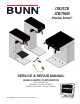
ITB/ITCB ICB/TWIN Infusion Series® SERVICE & REPAIR MANUAL BUNN-O-MATIC CORPORATION POST OFFICE BOX 3227 SPRINGFIELD, ILLINOIS 62708-3227 PHONE: (217) 529-6601 FAX: (217) 529-6644 42461.
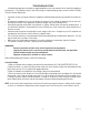
BUNN-O-MATIC COMMERCIAL PRODUCT WARRANTY Bunn-O-Matic Corp. (“BUNN”) warrants equipment manufactured by it as follows: 1) All equipment other than as specified below: 2 years parts and 1 year labor. 2) Electronic circuit and/or control boards: parts and labor for 3 years. 3) Compressors on refrigeration equipment: 5 years parts and 1 year labor.
INTRODUCTION This equipment will brew a half-gallon batch of coffee into an awaiting dispenser. It can be easily configured for 120V 15 amp, 120/208V 20 amp or 120/240V 20 amp. The brewer may have a hot water faucet for allied beverage use. It is only for indoor use on a sturdy counter or shelf. CONTENTS Warranty .............................................................................................................2 Contents.............................................................................
TROUBLESHOOTING A troubleshooting guide is provided to suggest probable causes and remedies for the most likely problems encountered. If the problem remains after exhausting the troubleshooting steps, contact the Bunn-O-Matic Technical Service Department. • • • • • • • Inspection, testing, and repair of electrical equipment should be performed only by qualified service personnel. All electronic components have ac line voltage and some have low voltage dc potential on their terminals.
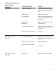
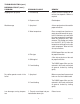
TROUBLESHOOTING (cont.) REFILL CIRCUIT PROBLEM PROBABLE CAUSE REMEDY Will not refill 1. Power off to brewer Press ENABLE BREW switch on control panel to determine if power is ON. 2. Water shut off Make sure water is ON. 3. Error Message Brewer has shut down due to malfunction (See Diagnostic Section in this manual). 4.ON/OFF Switch (If equipped) Make sure ON/OFF Switch is "ON" and indicator is lit. 5. Lime build up on Probe(s) Remove the Level Probe(s) and check for lime deposit on tip.
TROUBLESHOOTING (cont.) HEATING CIRCUIT PROBLEM PROBABLE CAUSE REMEDY Water does not heat to proper temperature 1. Display's error message Brewer has shut down due to malfunction. See Diagnostics. 2. Water not touching main (short) level probe Remove level probe and grommet. Look into hole on tank lid. Water must be within approximately one inch from top of tank. 3. Water Level Probe Sensing System Check refill circuit. Heaters will not turn on if water is not grounding level probe. 4.
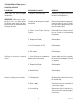
TROUBLESHOOTING (cont.) BREWING CIRCUIT PROBLEM Brew cycle will not start PROBABLE CAUSE 1. Display's error message REMEDY Brewer has shut down due to malfunction. See Diagnostics. 2. No water Water lines and valves to the brewer must be open. 3. No power or incorrect voltage to the brewer Check for voltage across the terminals at the terminal block. 4. ON/OFF switch not in the "ON" position The indicator lamp must be lit 5.
TROUBLESHOOTING (cont.) BREWING CIRCUIT (cont.) PROBLEM PROBABLE CAUSE REMEDY Dripping from sprayhead 1. Lime build up Inspect the tank assembly for excessive lime deposits. Delime as required. 2. Dispense valve Check/replace 1. Sprayhead A clean sprayhead must be used for proper extraction. 2. Water temperature Place an empty brew funnel on an empty decanter beneath the sprayhead. Initiate brew cycle and check the water temperature immediately below the sprayhead with a thermometer.
DIAGNOSTICS MESSAGE PROBABLE CAUSE REMEDY Temperature Too Low 1. Water temperature in the tank does not meet the ready temperature. A) Wait for the brewer to heat to the proper temperature. B) Disable the BREW LOCKOUT function. Refer to programming section for procedure. Heating Time Too Long 1. Tank Heater failure. Replace or repair as needed 2. Control Board/Thermistor failure Replace or repair as needed 1. Water shut off to brewer Check water supply shut-off 2.
COMPONENT ACCESS This section provides procedures for testing and replacing various major components used in this brewer should service become necessary. Refer to Troubleshooting for assistance in determining the cause of any problem. WARNING - Inspection, testing, and repair of electrical equipment should be performed only by qualified service personnel. The brewer should be unplugged when servicing, except when electrical tests are required and the test procedure specifically states to plug in the brewer.
CONTROL BOARD Removal and Replacement: 1. Disconnect brewer from power source. 2. Disconnect the wires from the relay on the control board. 3. Disconnect all of the connectors from the control board. 4. Remove the two nuts securing the control board to the hood. 5. Tilt the control board inward to clear the display section. 6. Place the bottom edge of the new control board in the cradle, tilt the board forward, and secure with the two nuts to the hood. 7. Re-install connectors. FIG.
MEMBRANE SWITCH NOTE: Pin 22 is the static shield & will not provide a reading to the other pins. There are two commons in this circuit, pins 9 & 10. Disconnect brewer from power source before disconnecting ribbon cable from control board. Removal and Replacement: 1. Disconnect the ribbon cable from the 22-pin connector on the control board. 2. Gently peel the membrane switch from the front face plate assembly. 4 Remove any adhesive that remains on the front face plate. 5.
BREW VALVE (EARLY MODELS) AND BYPASS VALVE ON ALL ICB's observed, brew valve is defective. Replace valve and test again to verify repair. If voltage is not present as described, refer to Wiring Diagrams and check the brewer wiring harness. Also check the control board and switch for proper operation. Removal and Replacement: 1. Disconnect the brewer from the power source. 2. Disconnect wires from the valve. 3. Drain enough water from the tank so the water level is below the outlet. 4.
BREW VALVE (LATE MODELS) Diagrams and check the brewer wiring harness. Also check the control board and membrane switch for proper operation. Removal and Replacement: 1. Disconnect the brewer from the power source. 2. Disconnect wires from the valve. 3. Drain enough water from the tank so the water level is below the outlet. 4. Remove sprayhead and hose from the valve. 5. Remove the nut securing the valve to the sprayhead panel. 6. Install new valve using the nut from step 5. 7.
REFILL VALVES If resistance is not present as described, replace the refill valve. If resistance is present as described, check for debris in the valve. Removal and Replacement: 1. Remove both wires from the refill valve. 2. Verify that the white shutoff clamp between valve and tank is squeezed shut. 3. Disconnect both water lines at the valve. 4. Remove the two screws securing the valve to the component mounting bracket. 5. Using the two screws, install the new valve to the component mounting bracket. 6.
REFILL VALVES EARLY ICB CURRENT ICB & & ITB Flow control used on dual dilution models only SCREEN EARLY ITCB STRAINER CURRENT ITCB & ITB-DD SCREEN STRAINER 16 42461 0911809
TANK HEATERS 2268W Large Dia. 1425W Small Dia. FIG. 17-2 DV TANK HEATERS HEATER RESISTANCE 1425W-120V 9.5-11.0 3500W-240V 15.1-17.6 1680W-120V 7.9-9.2 1800W-120V 7.4-8.7 2268W-120V 5.9-6.9 3000W-208V 12.9-15.1 3000W-240V 17.9-20.7 3500W-200V 10.5-12.2 TERMINAL TO SHEATH - INFINITE (OPEN) FIG. 17-1 ICB TWIN TANK HEATERS Location: The tank heaters are located inside the tank and secured to the tank bottom. Test Procedures: 1.
LIMIT THERMOSTAT FIG. 18-1 LIMIT THERMOSTAT Location: The limit thermostat is located on the tank lid (on the front of the tank on twins). FIG. 18-2 LIMIT THERMOSTATS Test Procedures: 1. Disconnect the brewer from the power source and allow to cool. 2. Disconnect the wires from the limit thermostat. 3. With an ohmmeter, check for continuity across the limit thermostat terminals. If continuity is present as described, the limit thermostat is operating properly.
TEMPERATURE PROBE FIG. 19-1 TEMPERATURE PROBE Location: The temperature probe is inserted through the tank lid assembly. FIG. 19-2 TEMPERATURE PROBE Test Procedures: 1. Disconnect the brewer from the power source. 2. With a DC voltmeter, check voltage across the two wires at J13 (J3 on ITB) on control board (black probe to black wire, red probe to white wire refer to FIG 19-2). Connect the brewer to the power source. The indication should be between 4vdc (cool) to 1vdc at ready temperature. 3.
TEMPERATURE PROBE 3. Press and hold the "Hidden" button until display reads "CAL TEMPERATURE SENSOR?" "NO/YES" 4. Select "YES". The display should show something similar to the screen below (FIG 20-2). NOTE: Variables such as tank set temperature could show different numbers than the example shown here. Tank must be at it's ready temp before calibrating. 5. Press the + (Control) button to increase or - (Digital) button to decrease temperature reading until it matches the reading on the thermometer. 6.
VOLTAGE SELECTOR SWITCH Removal and Replacement: 1. Disconnect the brewer from the power source. 2. Disconnect the three wires from the selector switch. 3. Remove the switch mounting nut from the under side of component mounting bracket; remove switch from bracket. 4. Install new switch in component mounting bracket and secure with mounting nut. FIG. 21-1 VOLTAGE SELECTOR SWITCH Location: The voltage selector switch is located on the component mounting bracket on the base plate. Test Procedure: 1.
POWER SWITCH Removal and Replacement: 1. Disconnect the brewer from the power source. 2. Disconnect the wires from the power switch. 3. Remove the switch mounting screws from the left side of trunk. 4. Install new switch in trunk with the two 6-32 x ¼˝ mounting screws. L2 L1 FIG. 22-1 POWER SWITCH (ICB SHOWN) Location: The power switch is located on the lower right side of the trunk (ICB) or lower rear panel (ITCB). FIG. 22-2 ROCKER SWITCH Test Procedure: 1. Disconnect the brewer from the power source.
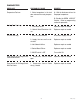
SCHEMATIC WIRING DIAGRAM iTCBA, iTCBB L2 GRN/YEL L1 RED BLK BLK RED EMI FILTER RED BLK BLK RED LIMIT THERMOSTAT BLU-14 BLK-14 TANK HEATER BLK-14 RED-14 RED-14 3500W BLK J1-1 J1-2 # / . 4 2 / , 0 # " / ! 2 $ COM N.O.
WHI GRN N L2 RED SCHEMATIC WIRING DIAGRAM ITCB-DV & ITCB-C-DV BLK L1 MAIN ON/OFF SWITCH (Late Models only) BLK-18 BLK-14 LIMIT THERMOSTAT BLU-14 BLK-14 (1425W ITCB-C-DV ONLY) TANK HEATER BLU-14 BLK-14 BLK COM N.O. J17-1 VIO TANK HEATER RED-14 1800W FUNNEL SENSOR 1 3 BRN/WHI WHI/VIO BLU-14 BLK-14 SOL WHI BRN/WHI WHI/VIO WHI/VIO WHI/GRN J17-5 WHI-14 WHI/VIO-14 1680W J1-1 J1-2 # / .
WHI Earth Ground N L2 RED SCHEMATIC WIRING DIAGRAM ITCB-DV & ITCB-C-DV Chassis Ground WITH FACTORY SWEETENER BLK L1 MAIN ON/OFF SWITCH (Late Models only) BLK-18 BLK-14 LIMIT THERMOSTAT BLU-14 BLK-14 BLK J1-1 J1-2 # / . 4 2 / , 0 # " / ! 2 $ COM N.O.
WHI GRN N L2 RED BLK L1 SCHEMATIC WIRING DIAGRAM ICB-DV MAIN ON/OFF SWITCH (Late Models only) BLK-18 BLK-14 LIMIT THERMOSTAT BLU-14 BLK-14 SELECTOR SWITCH BLK-14 BLK COM N.O. J17-1 VIO WHI/VIO-14 TANK HEATER FUNNEL SENSOR 1 3 RED-14 2268W WHI/VIO BLU-14 BLK-14 WHI/RED WHI/RED WHI/GRN J17-5 WHI-14 BLU-14 1680W J1-1 J1-2 # / .
GRN N L2 WHI BLK L1 RED SCHEMATIC WIRING DIAGRAM ICB TWIN MAIN ON/OFF SWITCH (Late Models only) BLK-18 BLK-14 LIMIT THERMOSTAT BLU-14 BLU-14 # / . 4 2 / , 0 # " / ! 2 $ LEFT FUNNEL SENSOR 1 3 J20-1 VIO J20-3 WHI/VIO RIGHT FUNNEL SENSOR 1 3 J21-1 YEL J21-3 WHI/YEL BLU-14 BLK-14 COM N.O.
SCHEMATIC WIRING DIAGRAM iCBA, iCBB L1 L2 GRN/YEL RED BLK BLK RED EMI FILTER RED BLK BLK RED LIMIT THERMOSTAT BLU-14 BLK-14 BLK-14 TANK HEATER RED-14 3500W BLK J1-1 J1-2 # / . 4 2 / , 0 # " / ! 2 $ COM N.O.
L1 L2 SCHEMATIC WIRING DIAGRAM ICB TWIN 230V Chassis Ground BLU BRN GRN/YEL TERM BLOCK BLK RED GRN EMI FILTER Chassis Ground BLK-18 BLK-14 LIMIT THERMOSTAT BLU-14 BLU-14 # / . 4 2 / , 0 # " / ! 2 $ LEFT FUNNEL SENSOR 1 3 J20-1 VIO J20-3 WHI/VIO J21-1 YEL J21-3 WHI/YEL BLU-14 BLK-14 COM N.O.
SCHEMATIC WIRING DIAGRAM ITB SINGLE & DUAL DILUTION MODELS AND MODELS w/OPTIONAL SWEETENER L2 L1 WHI BLK WHI TR-5 TR-2 # / .