BUNN® TECHNICAL TRAINING JDF Silver Series
Index Unit 1: Installation Site Requirements............................................................................................................... 4 Prepping Machine for Install.............................................................................................. 4 Install Outer Door Cover..................................................................................................... 4 Water Supply Install.................................................................................
Unit 1 Installation Unit Objectives Given a realistic scenario depicting a new site install, the learner will be able to install and setup the dispenser for customer turnover without error. Given a new machine, all the necessary tools and safety equipment, the learner will be able to install the dispenser without error. The learner will be able to verify that the site requirements have been met. The learner will be able to prepare the machine for install.
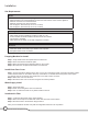
Installation Site Requirements Space • • • • • • Counter able to support 150 lbs. (68 kg) Minimal clearance is required between the machines side and the wall or another appliance Minimum clearance of 4” behind machine Minimum clearance of 8” above machine JDF-2S approx. dimensions (H 33 x W 10 x D 25.5) JDF-4S approx. dimensions (H 33 x W 16 x D 25.5) Plumbing • • • • • 3/8” flare water connection Water supply must be capable of producing 3 fluid oz.
Initial Fill CAUTION: The dispenser must be disconnected from the power source throughout the initial fill, except when specified in the instruction. Step 1. Remove drip tray assembly and splash panel from the dispenser. Replace the drip tray. Step 2. Connect the water source to the back of the dispenser. Step 3. Pull the fill tube from the dispenser, remove the plug and connect it to the dispense nozzle. Step 4. Set the Program Switch (near main control board) to the ON position.
Unit 2 Setup Unit Objectives Given a realistic scenario depicting a new site install, the learner will be able to install and setup the dispenser for customer turnover without error. Given an installed machine, all the necessary tools and safety equipment, the learner will be able to set the machine up for initial operation. The learner will be able to load the product. The learner will be able to prime the pumps. The learner will be able to perform a water flow test and adjustment.
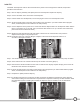
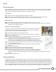
Setup Product Preparation Prior to calibrating the machine you must first load product and prime the pumps. The product must be completely thawed and be within the temperature range of 35º - 40º F. If the product is not within the acceptable temperature range you will not be able to calibrate the machine to the product correctly. Load Product Step 1: Mix the product by vigorously shaking the product container. Step 2: Wet or use a food grade lubricate on the container o-ring.
Calibration Process The following process needs to be completed for all dispense stations. Step 1: Identify the desired mix ratio for the product being used, (usually found on the product container), and mark the product ratio on the total dispense ratio chart. Step 2: Conduct water flow test to determine known volume of water dispensed. Step 3: Perform total dispense test to determine total volume of water and product dispensed.
Total Dispense Ratio Set Up Procedure Tools Required: • 64 ounce pitcher (BUNN P/N: 04238.0000) or graduated measuring cup (BUNN P/N: 33095.0000). Step 1: Reference recorded total dispense water for each dispense station. Step 2: Place the Program switch in the ON position. Step 3: Place a measuring container under the dispense nozzle, press and release the DISPENSE button 6 times. Step 4: Record the total ounces dispensed.
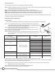
Ratio Target Chart 3 Second Water Dispense (oz.) Ratio Target 2:1 3:1 4:1 5:1 6:1 7:1 8:1 9:1 10:1 11:1 12:1 13:1 14:1 15:1 1.5 2.25 2.00 1.88 1.80 1.75 1.71 1.69 1.67 1.65 1.64 1.63 1.62 1.61 1.60 1.75 2.63 2.33 2.19 2.10 2.04 2.00 1.97 1.94 1.93 1.91 1.89 1.88 1.88 1.87 2.0 3.00 2.67 2.50 2.40 2.33 2.29 2.25 2.22 2.20 2.18 2.17 2.15 2.14 2.13 2.25 3.38 3.00 2.81 2.70 2.63 2.27 2.53 2.50 2.48 2.45 2.44 2.42 2.41 2.40 2.5 3.75 3.
Unit 3 Machine Composition Unit Objectives Given a realistic scenario in which the learner has access to the machine’s internal components the learner will understand the composition and functions of the dispenser. Given a realistic scenario requiring the learner to access the internal components of the machine the learner will be able to remove panels. Given an operating machine the learner will be able to give a general explanation of how the unit operates.
Machine Composition Exterior Overview Inlets, Control Switches, Product Outlets, and Removable Parts • • • • • • • Water Inlet Air Filter Dispense Lockout Switch Dispense Nozzle (Quick Stop) Drip Tray Splash Panel (electrical schematic is located on backside of splash panel) Cold Water Nozzle (option only available JDF-4S) Air Filter Dispense Nozzle Splash Panel Drip Tray User Interface The user interface allows the customer to dispense a beverage.
Accessing the Inside of the Machine The majority of service work done to a JDF-S will require the service technician to access the inside of the unit. The unit has four removable panels to facilitate access- the top panel, the two side panels, and front splash panel. Depending on the repair the technician may have to remove one or all of these panels. In order to work safely the power should be disconnected prior to removal of any body panel.
Both transformers are 120VAC on the primary side and step the voltage down to 24VAC on the secondary side of the transformer. Each transformer is protected on the “load” side with a resettable PTC fuse. The Poly Switch Polymeric Positive Temperature Coefficient (PPTC) device used on the load side of the transformers will help protect against harmful over/current surges, voltage and over/temperature faults. The PPTC device will reset after the fault is cleared and power to the circuit is removed.
Connectors and pump speed dials not present on JDF-2 S, CBA (BUNN P/N: 40177.1001) • J-12 • J-13 • J-15 Pump Speed Dial 3 and 4 Refrigeration Switch (F) The refrigeration switch is located behind the splash panel next to the circuit board. This switch passes 120VAC power to the water bath pump and compressor K1 relay contact terminal. Program Switch (G) The program switch is located near the main control board next to the refrigeration switch.
Refrigeration System The components that make up the refrigeration system to create an ice bank are compressor (1), filter dryer with capillary tube (2), condenser (3), condenser fan (4), evaporator (5) and accumulator (6). The other components that are responsible for monitoring the ice bank and turning on/off of the compressor are as follows; thermistor (7), start relay (8), run relay, transformer and main control board.
Pump Assembly Bypass The bypass holes are used for increased agitation in the water tank which has an additional purpose of enhancing the performance and burst capacity of the machine. Both pumps are identical in appearance but have two different service replacement part numbers. Single hole is used in the JDF-2S and the two hole bypass is used in the JDF-4S.
Dispense Platform The modular dispense platform pumps and mixes 2+1 to 11+1 concentrated beverages including 4+1 high viscosity and 5+1 juices accurately and consistently. The High Intensity dispense valve mixes and dispenses product at a rate of 1.0 to 1.5 ounces per second. The rpm for the dispense motor are set by potentiometers on the CBA. The potentiometers range from 9.0 to 25.0 VDC. The advantage to modular dispense platforms is removal and ease of service.
Unit 4 Preventive Maintenance Unit Objectives Given a realistic scenario depicting a machine requiring a preventive maintenance, the learner will be able to identify which elements of a component need to be serviced without error. Given a machine, all the necessary tools and safety equipment, the learner will be able to identify the components that need to be serviced for the PM.
Preventive Maintenance In order to maintain proper operation and long service life BUNN recommends performing the preventive maintenance every 6 months. Individual customers will vary with some customers choosing not to receive preventive maintenance. Some of the PM items may require more frequent maintenance depending on the site conditions.
□□ Using a flashlight, shine the light through the condenser fins to re-check for cleanliness or dirt between the fins. □□ Heavy build-up of grease in the condenser may require the use of a commercial condenser cleaner. □□ Follow the manufacture warning and safety instructions along with how to instructions supplied with the cleaner. Step 5: Replacing the peristaltic pump tubing. □□ Open dispenser door. □□ Remove all product containers and place them in a refrigerated, (35-40º F [1.6-4.4º C]), environment.
□□ Total Dispense Test Step 1: Place the pitcher beneath the dispense nozzle you are testing. Step 2: Place the “Dispense Lockout” switch in the Off position and access the internal program switch and turn ON. Step 3: Press and release the dispense button, (“Stop/Plus” button if using portion control option), 6 times. Step 4: Measure the amount of liquid dispensed. Step 5: Mark the quantity of liquid dispensed on the total dispense ratio chart.
Unit 5 Troubleshooting Unit Objectives Given a realistic scenario depicting a broken machine, the learner will be able to effectively diagnosis, troubleshoot, and repair the problem returning the machine to normal operation. Given a dispenser having a fault condition, all the necessary tools and safety equipment, the learner will be able to diagnose the symptom to the actual problem. The leaner will be able to access the fault indicators.
Troubleshooting and Repair The JDF 2S and 4S dispensers have built in function LED indicators on the main CBA. The indicators, located at the bottom of the CBA, indicate a function when lighted or could mean a fault status by a flashing sequence. The circuit board LED indicator chart found in the JDF 2S and JDF 4S Installation & Operating Guide should be referenced when diagnosing a fault. LED Indicator Chart LED Number LED Color Illuminates 1 Bath Red When bath temperature is above 34º F.
Mechanical or Refrigeration Failure If a repair to the refrigeration system is needed it is required that a certified refrigerant technician handles the repair. When troubleshooting and repairing any unit with a refrigeration system, the servicing technician needs to check all possible mechanical failures before contacting a certified refrigerant technician. The JDF 2S and 4S has one symptom, bath not freezing, where it could be a failure with the refrigeration system.
Bath Not Freezing Compressor is not running or low refrigerant charge. Step 1: Check refrigeration switch is turned on and passing 120VAC to red/black wire on one side of the K1 relay contact. Yes: Go to the next step. No: Replace the switch or check for a loose wire in the circuit. Step 2: Verify condenser filter is clean and proper ventilation around machine for optimum performance. Step 3: Determine if the compressor is activating after 6 minute delay from initial plug-in.
Resource Material Cabinet Thermistor R-T Conversion Table R0=5.65K? B0/25=3383K TX (°C) -40 -39 -38 -37 -36 -35 -34 -33 -32 -31 -30 -29 -28 -27 -26 -25 -24 -23 -22 -21 -20 -19 -18 -17 -16 -15 -14 -13 -12 -11 -10 -9 -8 -7 -6 -5 -4 -3 -2 -1 0 Rnom (K? ) 44.17 41.65 39.29 37.08 35.02 33.09 31.26 29.55 27.95 26.44 25.04 23.71 22.45 21.28 20.17 19.13 18.15 17.22 16.35 15.52 14.75 14.01 13.32 12.67 12.05 11.47 10.92 10.40 9.903 9.432 8.989 8.570 8.171 7.797 7.439 7.101 6.780 6.475 6.185 5.911 5.
Bath Thermistor PART NO.: 28891-0000 TEMP (âF) 28 30.00 31.00 32.00 33.00 34.00 35.00 36.00 37.00 38.00 39.00 40.00 41.00 42.00 43.00 44.00 45.00 46.00 47.00 48.00 49.00 50.00 51.00 52.00 53.00 54.00 55.00 56.00 57.00 58.00 59.00 60.00 61.00 62.00 63.00 64.00 65.00 66.00 67.00 68.00 69.00 70.00 71.00 72.00 73.00 74.00 75.00 76.00 77.00 78.00 79.00 80.00 81.00 82.00 83.00 84.00 85.00 86.00 87.00 88.00 89.00 90.00 91.00 92.00 93.00 94.00 95.00 96.00 97.00 98.00 99.00 100.00 101.00 102.00 103.00 104.
PART NO.: 28891-0000 105.00 106.00 107.00 108.00 109.00 110.00 111.00 112.00 113.00 114.00 115.00 116.00 117.00 118.00 119.00 120.00 121.00 122.00 123.00 124.00 125.00 126.00 127.00 128.00 129.00 130.00 131.00 132.00 133.00 134.00 135.00 136.00 137.00 138.00 139.00 140.00 141.00 142.00 143.00 144.00 145.00 146.00 147.00 148.00 149.00 150.00 151.00 152.00 153.00 154.00 155.00 156.00 157.00 158.00 159.00 160.00 161.00 162.00 163.00 164.00 165.00 166.00 167.00 168.00 169.00 170.00 171.00 172.00 173.00 174.
PART NO.: 28891-0000 184.00 185.00 186.00 187.00 188.00 189.00 190.00 191.00 192.00 193.00 194.00 195.00 196.00 197.00 198.00 199.00 200.00 201.00 202.00 203.00 204.00 205.00 206.00 207.00 208.00 209.00 210.00 211.00 212.00 30 1089.00 1070.00 1052.00 1034.00 1016.00 998.00 981.00 964.00 948.00 932.00 916.00 900.00 885.00 870.00 856.00 841.00 827.00 814.00 800.00 787.00 774.00 761.00 749.00 736.00 724.00 713.00 701.00 690.00 678.00 3 JDF Silver Series Training Manual DATE:11AUG98 1040.00 1022.00 1004.