LCR-2 LCR-2A LCR-2 PC LCR-2A PC ER W PO Y AD RE N IO RT PO E NS RI LL FI RE ! OP ST ER T HO ES EM ISS RT IDS G NIN ! T EN UID LIQ WAT DS AU CH E AV IQU TL HO AR ! W INSTALLATION & OPERATING GUIDE BUNN-O-MATIC CORPORATION POST OFFICE BOX 3227 SPRINGFIELD, ILLINOIS 62708-3227 PHONE: (217) 529-6601 FAX: (217) 529-6644 To ensure you have the latest revision of the Operating Manual, or to view the Illustrated Parts Catalog, Programming Manual, or Service Manual, please visit the B
BUNN-O-MATIC COMMERCIAL PRODUCT WARRANTY Bunn-O-Matic Corp. (“BUNN”) warrants equipment manufactured by it as follows: 1) Airpots, thermal carafes, decanters, GPR servers, iced tea/coffee dispensers, MCP/MCA pod brewers thermal servers and Thermofresh servers (mechanical and digital)- 1 year parts and 1 year labor. 2) All other equipment - 2 years parts and 1 year labor plus added warranties as specified below: a) Electronic circuit and/or control boards - parts and labor for 3 years.
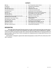
CONTENTS Warranty........................................................................... 2 Introduction...................................................................... 3 User Notices..................................................................... 4 Electrical Requirements.................................................... 5 Plumbing Requirements................................................... 6 CE Requirements.............................................................. 6 Initial Set-up.
USER NOTICES Carefully read and follow all notices on the equipment and in this manual. They were written for your protection. All notices are to be kept in good condition. Replace any unreadable or damaged labels. As directed in the International Plumbing Code of the International Code Council and the Food Code Manual of the Food and Drug Administration (FDA), this equipment must be installed with adequate backflow prevention to comply with federal, state and local codes.
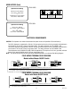
USER NOTICES (Cont) FOR 3-PHASE OPERATION CONNECT INPUT WIRING TO L1,L2,L3 & N AS SHOWN. FOR 1-PHASE/30 AMP. OPERATION MOVE BLACK WIRE INTO TERMINAL BLOCK WITH BROWN WIRE, CONNECT INPUT WIRING TO L1 & N AS SHOWN. L3 L1 L2 RED BLU L1 N FROM POWER SOURCE N BLK N BLU BRN TO MACHINE RED FROM POWER SOURCE L1 L2 L1 L3 N TERMINAL BLOCK N L3 BRN BLK TO MACHINE L2 FROM POWER SOURCE BLU L1 RED L1 L2 208-240 V, 25.8 A, 6200 W 1PH, 2-Wire + GND, 60HZ or 120/208-240 V, 25.
ELECTRICAL REQUIREMENTS (Cont.) FOR 3-PHASE OPERATION CONNECT INPUT WIRING TO L1,L2,L3 & N AS SHOWN. The LCR-2A dispenser is internally wired from the factory for 230 Volts AC Single Phase 50/60 Hz. It requires a 2-wire, grounded, individual branch circuit rated for 230 Volts AC. FOR 1-PHASE/30 AMP. OPERATION MOVE BLACK WIRE INTO TERMINAL BLOCK WITH BROWN WIRE, CONNECT INPUT WIRING TO L1 & N AS SHOWN.
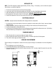
INITIAL SET-UP NOTE: The LCR-2 dispenser weighs approximately 100 lbs. (45 kg). If necessary, use more than one person when lifting or moving the dispenser. 1. 2. 3. 4. 5. Cut the two straps and remove the box and foam packing. Locate and remove the information packets and tube kits from top of packaging and set aside. Open the dispenser door and remove the drip tray and the lower splash guard panel. Set dispenser on the counter where it is to be used. CAUTION: DO NOT LIFT ON THE DOOR.
INSTALLING THE DRIP TRAY AND FLIP DOWN CUP TRAY • Place the SST Cover in the recessed area of the Drip Pan. • Slide the Drip Pan under the front of the LCR-2 and align the tabs with the legs. • Insert the hinge pins of the Cup Tray into the notched bracket on the splash panel and rotate the Tray into place. • The Cup Tray should be down for serving individual cups of coffee. • The Cup Tray can be flipped up out of the way for filling carafe’s and/or airpots.
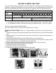
SELECTING THE CORRECT PUMP TUBING There are two pump tube sizes available for use with this dispenser. To determine the correct tubing for your application, first determine the dispenser flow rate you intend to use, refer to Setting Dispenser Flow Rate. Then look up the recommended tube size for the mix ratio of your concentrate, refer to the Tube Selection Chart. Dispense Rate 1.8 Oz/sec. (53 ml/sec.) 2.5 Oz/sec. (74 ml/sec.
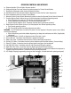
OPERATING CONTROLS AND INTERFACE 1a. Dispense Handles: Pull and Hold to dispense product. 1b. Dispense Switches: Push and Release to dispense product for Portion Control Models. 2. Stop Switch: Momentary switch stops all dispense functions. 3a. Hot Water Switch: Push and Hold switch to dispense hot water from the center dispense tip. 3b. Push and Release switch for Portion Control Models. 4. Alternate Portion Control Switch: Momentarily pushed to select the Alternate Portion Control Volume #2. 5.
SETTING DISPENSER FLOW RATE The dispenser comes from the factory with flow restrictors in the mix chambers. With the restrictors in place the dispense rate is about 1.8 oz./sec (53.2 ml/sec) and is used primarily for cup at a time dispensing. The flow restrictors can be removed to increase the dispense rate to about 2.5 oz./sec (74 ml/sec) for larger volume dispensing (airpots, carafes, etc.). NOTE: The hot water FlowRate is fixed at approximately 1.7 oz/sec. and can not be adjusted.
ADJUSTING MIX RATIOS The dispenser comes with the Mix Ratios preset to 35:1. The Left and Right ratios can be set for any ratios between 20:1 and 100:1, (refer the concentrate package or the supplier for the recommended ratio). Once the recommended ratio has been entered, the Ratios can be adjusted to suit local taste preferences (i.e. lighter or darker).
FlavorGard™ Feature FlavorGard™ is a patented feed back control loop that monitors the mixed product and adjusts the concentrate delivery rate to maintain a consistent mix profile, i.e. Flavor Profile. The system consists of a conductance probe mounted in the final stages of the mixing chamber, a metering pump with RPM sensor and a digital controller.
Rinse Procedure: 1. Open the cabinet door and select Rinse on the Function Selector switch – close the door. 2. Place a 2 Liter (1/2 Gal) container under the Left dispense tip. 3. Activate the Left dispense until water flow stops automatically, approximately 20 sec. 4. Repeat Steps 2 & 3 for the Right dispense tip. The Rinse LED will turn OFF, when the Rinse procedure has been satisfied for both sides. 5. Open the cabinet door and select Normal on the Function Selector switch – close the door.
PROGRAMMING THE DISPENSER Remove the lower splash guard assembly to access the digital programming module with LCD display. Press the Down Arrow key to inter the programming menu. Use the Up and Down Arrow keys to scroll through the menu screens. Select Exit to leave the programming function and return to normal operations. NOTE 1: Flashing menu items indicate which selection is active. NOTE 2: Values shown below are the factory default values for English units. NOTE 3: Values in [X - X] are the Min.
MENU SCREEN ACTION LOCK FLAVOR ? EXIT YES FLAVORS LOCKED EXIT DESCRIPTION Select (YES) or (EXIT) Select YES, to Lock In sensor calibration. NOTE: Display will return to “Find LF Target” if sensor calibration is out of range. NONE Confirms that sensor calibration was in range and accepted. Scroll down to continue.
MENU SCREEN ACTION DESCRIPTION TANK TEMP 180 (-) EXIT (+) Use the (+) or (-) buttons to Sets the water Tank temperature [120 - 200°F] adjust the target Temp. or [49 - 93°C] READY TEMP 175 (-) EXIT (+) Use the (+) or (-) buttons to Sets the hot water Ready temperature. Typically adjust the target Temp. set to the minimum desired dispense temp. CABINET TEMP 38 (-) EXIT (+) Use the (+) or (-) buttons to Sets the Chilled Cabinet target temperature [38 adjust the target Temp.
MENU SCREEN ACTION RINSE TIME ? (-) 12 Hrs (+) DESCRIPTION Use the (+) or (-) buttons to Enter the desired time between required Rinse adjust Rinse Alarm delay Cycles in hours, [8 - 24 hrs.] RINSE LOCKOUT ? NO EXIT YES Select (YES) to enable Select YES to Lockout dispensing until the Rinse Alarm has been cleared.
MENU SCREEN ACTION DESCRIPTION If NO - skip to next menu. CAL RIGHT PUMP ? PULL DISPENSER Place a 50 mL (#34843.1000) The Right Pump will dispense concentrate for graduated cylinder under 20 seconds, then shut off automatically. Collect the Right dispense tip, then and measure the concentrate dispensed. activate the Right Dispenser CAL RT PUMP VOL (-) 43mL (+) Use the (+) or (-) buttons to Enter the volume of concentrate measured from enter volume collected the Right Pump in mL(not Oz.
MENU SCREEN ACTION DESCRIPTION BIB EMPTY -> 500 (-) EXIT (+) Use the (+) or (-) buttons to Used to set the Conductance Threshold for the adjust empty BIB threshold Empty BIB warning. Default is 500 XX REFILL -> 155 (-) EXIT (+) Use the (+) or (-) buttons to Used to set the Conductance Threshold for the adjust Refill threshold Tank Refill Probe. WTR START DELAY (-) .15SEC (+) Use the (+) or (-) buttons to Dispense Valve ON Delay.
INITIAL FILL & HEAT 1. Select Normal on the Function Selector Switch and Run on the Mode Selector Switch. 2. Confirm the water supply is on. 3. Connect the dispenser to the power source. The Red POWER LED will illuminate and water will begin flowing into the tank. The dispenser will automatically stop filling when the tank is full. The dispenser will not begin heating the water until after the tank is filled. Dispenser models with product chillers will begin to cool the cabinet at this time. 4.
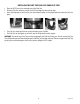
LOADING THE CONCENTRATE 1. Thoroughly mix concentrate by vigorously shaking the product Bag-In-Box (BIB). 2. Pull the BIB connector through the hole provided in the box and place it on the drip tray with the connector facing up. (See Fig. 1) 3. Open the dispenser door and locate the appropriate left or right BIB Adapter fitting. 4. Pull the Adapter fitting down and connect it to the BIB. (See Fig. 2) 5. Place the BIB upright in the machine, rotating it into position with the connector facing forward.
OPERATING THE PULL & HOLD DISPENSER (Models LCR-2, LCR-2C, LCR-2A) Set the Function Selector Switch to Normal and the Mode Selector Switch to Run. 1. Pull and Hold Dispense Mode (Cup at a time) a. Place cup on the cup tray beneath the desired dispensing tip. For a large container, flip the cup tray up and place the container on top of the drip tray. b. Pull and Hold the corresponding dispense handle until the cup or other container is full. c. Remove cup or container. 2.
OPERATING THE PRESET PORTION CONTROL DISPENSER (Models LCR-2 PC, LCR-2C PC, LCR-2A PC) Set the Function Selector Switch to Normal and the Mode Selector Switch to Run. Dispensing Preset Portions of Coffee or Hot Water 1. Primary Volume Portion Dispense Mode. (Volume 1) Refer to Programming Functions on how to set this amount. a. Place cup on the cup tray beneath the desired dispensing tip. For a large container, flip the cup tray up and place the container on top of the drip tray. b.
CLEANING & PREVENTATIVE MAINTENANCE General Cleaning and Sanitizing Procedures Note: The BUNN® Liquid Coffee Dispenser incorporates a “user selectable” rinse reminder feature, which lights the Rinse LED on the front panel and disables dispensing when it is time to rinse. See Programming Functions to activate this feature. Daily: RINSING 1. Open the dispenser door. 2. Select Rinse on the Function Selector Switch and Run on the Mode Selector Switch. 3. Close the dispenser door. 4.
PREVENTIVE MAINTENANCE Bunn-O-Matic Corporation recommends that preventive maintenance be performed at regular intervals. Maintenance should be performed by a qualified service technician. For Technical Service, contact Bunn-O-Matic® Corporation at 1-800-286-6070. NOTE: Replacement parts or service caused by failure to perform required maintenance is not covered by warranty. Replace pump hoses every 6-Months or as needed.
DRAINING THE HOT WATER TANK CAUTION: The dispenser must be disconnected from the power source throughout these steps. 1. Disconnect the dispenser from the power source. 2. Shut off and disconnect the incoming water supply. 3. Remove the front splash panel. 4. Pull out drain tube to empty into a sink or a container with a minimum of five-gallon capacity. 5. Make sure drain clamp is closed. Then, remove drain plug. 6. Direct tube into sink or container and open drain clamp.
Troubleshooting A troubleshooting guide is provided to suggest probable causes and remedies for the most likely problems encountered. If the problem remains after exhausting the troubleshooting steps, contact the Bunn-O-Matic Technical Service Department. • Only qualified service personnel should perform inspection, testing, and repair of electrical equipment. • Shorting the terminals or the application of external voltages to electronic components may result in component or circuit board failure.
Troubleshooting (Continued) Left Refill LED “ON” Left BIB Empty Concentrate BIB is Empty. BIB Not properly connected Tubing kinked or blocked Empty BIB warning set too high Replace BIB, see Loading the Concentrate Check BIB Connector Fittings Check Tubing Installation Check Threshold, see Field Calibrating the Emoty BIB Warning Right Refill LED “ON” Right BIB Empty Concentrate BIB is Empty.
Troubleshooting (Continued) Dispenser Diagnostics-LCD Display Screen Displayed Possible Cause Troubleshooting Procedures LF TARGET RPM TOO HIGH !! 1. The Tube Size selected for the Left Refer to “Selecting the Correct Pump Hand Dispenser is too small for the Tubing” section of the manual. application. TUBE TOO SMALL CHECK DISP RATIO 2. The Ratio selected for the Left Hand Refer to recommended Dispense Ratio Dispenser is not correct for the on the product label. application.
Troubleshooting (Continued) Screen Displayed Possible Cause Troubleshooting Procedures LEFT BIB EMPTY! REPLACE PRODUCT CHECK THRESHOLD RIGHT BIB EMPTY! REPLACE PRODUCT CHECK THRESHOLD OVERFLOW CUP FULL. EMPTY CUP HEATING TIME TOO LONG CHECK HEATING CIRCUIT FILL TIME TOO LONG CHECK WATER SUPPLY 1. Concentrate BIB is Empty. Replace BIB, see loading the Concentrate 2. BIB Not properly connected. Check BIB Connector Fittings 3. Tubing kinked or blocked. Check Tubing installation 4.
Troubleshooting (Continued) Screen Displayed Possible Cause Troubleshooting Procedures 1. C o r r e s p o n d i n g Te m p e r a t u r e Sensor Probe wire(s) broken or disconnected. 2. Product cabinet temperature too low. Service Required Service Required CHECK WIRE FOR SHORTS 1. Corresponding Temperature Sensor Probe wire(s) shorted to housing, or to each other. 2. Product cabinet temperature too high. EVAP TEMP SENSOR OUT OF RANGE 1.
Field Calibration of the Concentrate Pumps / Dispenser Flow Rates The factory set Default Values for the Pump & Dispenser Flow Rates are very accurate and typically do not need to be field calibrated. However, if the mix ratio accuracy is ever in question, this procedure can be used to recalibrate the unit in the field. Equipment Required: 50 to 100 ml graduated cylinder, with 1 ml graduations. 64 Oz (2000 ml) graduated container.
Field Calibration of the Concentrate Pumps / Dispenser Flow Rates (Continued) Dispenser Flow Rate Calibration 13. Press Down Arrow Key to display the CAL LF WTR FLO menu screen. 14. Place a 64 Oz (2000 ml) graduated container under Left Dispense Tip and Pull the Left Dispense Handle momentarily. The dispenser will dispense water for 20 seconds and then shut OFF automatically. 15. Keep the graduated container under dispense tip until all the water stops dripping. 16.
Field Calibrating the Empty BIB Warning The dispenser will automatically turn on the Left or Right “REFILL LED”, see Operating Controls and Interface, when the corresponding BIB is Empty. The Refill message is triggered when the FlavorGardTM sensor reading drops below the minimum setting. The factory set minimum is 500 and should be correct for most locations. However, in some areas the hardness of the local water supply may effect this reading.
SCHEMATIC WIRING DIAGRAM LCR-2/LCR-2, PC/LCR-2C/LCR-2C, PC (Older models may not have the Master Sw. and/or 10 Amp Fuses) BLK-14 Early Models SW.
SCHEMATIC WIRING DIAGRAM LCR-2A/LCR-2A, PC CAPACITOR .01uF GRN L1 CAPACITOR .01uF GRN GRN RFI SUPPRESION CAPACITOR 2.2uF BLK BLK BLK-14 DOUBLE POLE LIMIT THERMOSTAT 1 2 Early Models SW.
36026.