ULTRA-1 ULTRA-2 SERVICE & REPAIR MANUAL BUNN-O-MATIC CORPORATION POST OFFICE BOX 3227 SPRINGFIELD, ILLINOIS 62708-3227 PHONE: (217) 529-6601 FAX: (217) 529-6644 41084.
BUNN-O-MATIC COMMERCIAL PRODUCT WARRANTY Bunn-O-Matic Corp. (“BUNN”) warrants equipment manufactured by it as follows: 1) All equipment other than as specified below: 2 years parts and 1 year labor. 2) Electronic circuit and/or control boards: parts and labor for 3 years. 3) Compressors on refrigeration equipment: 5 years parts and 1 year labor.
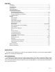
CONTENTS Warranty....................................................................................................................................2 User Notices..............................................................................................................................3 Site Preparation ........................................................................................................................3 Introduction.....................................................................
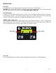
INTRODUCTION Safety first! To avoid electrical shock, unplug dispenser from power source before servicing inside. WARNING: When powered, the condenser cooling fan will turn on every 30 minutes to aid cooling the entire unit, even when not in the ICE or CHILL modes. KEEP HANDS AWAY FROM FAN! Basic Maintenance In order to maintain proper machine operation, the shaft seals and bushings need to be replaced as a Preventative Maintenance measure. A reminder message will appear every 6 months.
TEMP & TORQUE SCREEN Press and hold for five seconds the ULTRA and ICE hidden switches to display the TEMP & TORQUE. The temperature of each cooling drum and the hot gas temperature will toggle back and forth. The auger torque is displayed continuously. Press and release the ULTRA and ICE hidden switches to return to HOME SCREEN. The TEMP & TORQUE mode is typically used for service.
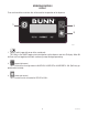
OPERATING CONTROLS ULTRA-1 There are three of these switches that will be used for the operation of the dispenser. 1 2 3 P3932 1. switch (upper left corner of the control pad) This switch is the ON/OFF toggle switch which powers up the dispenser and the LCD display. When ON the Date and Time toggle back and forth continously except during programming. 2. (upper right corner) This is used to turn the auger motor to AUGER ON, AUGER OFF or AUGER REFILL ON. (Refill only applicable when installed) 3.
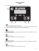
OPERATING CONTROLS ULTRA-2 There are five of these switches that will be used for the operation of the dispenser. 1 P3677 2 3 4 5 1. switch (upper left corner of the control pad) This switch is the ON/OFF toggle switch which powers up the dispenser and the LCD display. When ON the Date and Time toggle back and forth continously except during programming. 2. (bottom left corner) This is used to turn the left side auger motor to AUGER ON, AUGER OFF or AUGER REFILL ON.
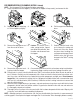
RECOMMENDED DAILY CLEANING (ULTRA-2 shown) NOTE – Turn the power OFF to the dispenser before proceeding. 1. Empty all product from the hopper(s). Disconnect the hopper lid lamp cord(s) and remove the lids. 2. Depress the hopper lock plung- 3. er. Lift the hopper up slightly. Pull forward to remove. 4. Pull the auger from the cooling drum. 5. Remove the cooling drum seal 6. from the rear of the drum. Caution: The faucet valve is 7. under spring tension.
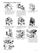
RECOMMENDED DAILY CLEANING (Continued) 1. Install the seal(s) over the 2. flange at the rear of the cooling drum(s) and press the seal(s) firmly into place as shown. Align the auger shaft(s) with the 3. auger(s). Push the auger(s) as far as they will go and rotate so the flat face of the auger shaft is aligned with the flat face of the auger nose. Install auger nose bushing into inside front of hopper. 4. Thoroughly rinse the hopper(s) 5. and install over the auger(s) and cooling drum(s).
Auto-fill Cleaning Instructions (With Brixing Pump Installed) Materials required 1. Non-sudsing liquid detergent (such as common household automatic dishwasher liquid detergent). 2. Household bleach (Sodium chloride solution: 5.25%) or equivalent. 3. Clean five (5) gallon bucket. 4. Measuring Cup 5. An adaptor is needed to hold the Q.C.D. (Quick Connect/Disconnect) fitting on the concentrate suction line open. A connector from an empty bag will work. Sanitizing Procedure 1.
PREVENTIVE MAINTENANCE A common problem occurs when the proper preventive maintenance procedures are not followed. Failure to perform these procedures may result in damaged equipment and may not be covered by warranty. Please check the following items before assuming a refrigeration fault. When the product does not freeze, there are several possibilities other than a failure in the refrigeration system.
REQUIRED REGULAR MAINTENANCE: Semi Annual: Auger Motor Cover Bunn Kit #34245.0002 is required for ULTRA-1 and #34245.0000 & #34245.0001 is required for ULTRA-2, to perform the semi annual Preventive maintenance: Note: Service caused by failure to perform required maintenance is not covered by warranty. The following instructions apply to one hopper only; repeat each step for all hoppers. Run Capacitor Auger Motor Assy Auger Shaft Assy Kit Contents Inventory this kit for completeness before proceeding.
REQUIRED REGULAR MAINTENANCE (Continued) 6. Pull the auger shaft assembly straight out of cooling drum. Inspect the shaft for abnormal wear. Open face of seal 7. From the front of dispenser, remove the seal and blue bushing away from tool from cooling drum and discard them. 8. Inspect inside of the coling drum from the rear for product leakage and clean thoroughly with an extended bristle brush (Bunn part no. 40500.1068) and warm sanitize solution, rinse and dry with a towel.
TROUBLESHOOTING A troubleshooting guide is provided to suggest probable causes and remedies for the most likely problems encountered. If the problem remains after exhausting the troubleshooting steps, contact the Bunn-O-Matic Technical Service Department. • • • • Inspection, testing, and repair of electrical equipment should be performed only by qualified service personnel. All electronic components have 120 volt ac and/or low voltage dc potential on their terminals.
TROUBLESHOOTING (cont.) Chills but won’t freeze Dispenser in “DAY” mode? No Set into “DAY” mode Yes Dispenser in “ICE” mode? Yes No 1 Verify augers are turned on Is display showing UPPER CASE “ICE” mode? No Is Thickness screen set low? Set into “ICE” mode Yes 1 Is Brix level high? No Yes Yes 2 No 2 Is Filter dirty? Inspect auger drive shafts for weak torsion springs or damaged pins. Check for dirty or worn seals and bushings.
TROUBLESHOOTING (cont.) No cooling at all Is ICE/CHILL set to off? Yes No Set into “ICE” or “CHILL” mode Is compressor running? No 1 Yes Yes Is filter dirty? Is Dispenser on an extension cord? Plug directly inti outlet No No Yes 3 1 No Call a licensed electrician Is there correct voltage at outlet? Check fan Yes Have a certified refrigeration technician check for low refrigerant or blockage. Follow compressor circuit checks.
TROUBLESHOOTING (cont.) Freezes, but not thick enough Too much alcohol in product Brix ratio too high Adjust thickness screen higher Check for slightly bent auger shaft pins and/or weak torsion springs. Check for dirty or worn seals and bushings.
TROUBLESHOOTING (cont.) Noise Auger jumping Using auger assembly from CDS 2 or 3? Check fan Lower brix ratio Replace with ULTRA p/n 32106.
TROUBLESHOOTING (cont.
TROUBLESHOOTING (cont.) Temperature Sensor Error TEMPERATURE SENSOR OPEN TEMPERATURE SENSOR SHORTED Left side Left side Right side Right side Product not covering back end of drum. Drum temperature falls below 9° F.
TROUBLESHOOTING (cont.) Clean Filter Messages “MONTHLY FILTER CLEAN REQUIRED” “FILTER NEEDS CLEANING” “FILTER NEEDS !!!CLEANING!!!” Freezing is Disabled Monthly reminder Clean filter Hot gas thermistor sensing over 220° F Hot gas thermistor sensing over 250° F Dirty filter; air flow blockage; wrong refrigerant or over charged Hold ULTRA button for 3 seconds to reset.
SERVICE This section provides procedures for testing and replacing various major components used in this dispenser should service become necessary. Refer to Troubleshooting for assistance in determining the cause of any problem. WARNING - Inspection, testing, and repair of electrical equipment should be performed only by qualified service personnel.
SERVICE(cont.) Removal and Replacement 1. Remove the two #8 locking screws securing the auger motor cover to the cooling drum mount assembly. 2. Remove the cover and set aside for reassembly. 3. Remove the #8 locking screw on the lower right side of the auger motor mounting bracket securing the auger motor run capacitor. Set capacitor aside with wires attached. 4. Disconnect the auger motor terminal from the terminal on the main wiring harness. 5.
SERVICE (cont.) AUGER MOTOR CAPACITOR Removal and Replacement 1. Remove the two #8 locking screws securing the auger motor cover to the cooling drum mount assy. 2. Remove the cover and set aside for reassembly. 3. Disconnect the wires from the auger motor capacitor terminals. 4. Remove the #8 locking screw on the lower right side of the auger motor mounting bracket securing the auger motor capacitor. 5.
SERVICE (cont.) 7. Pull the auger shaft assembly straight out of cooling drum. Inspect the shaft for abnormal wear or scoring. 8. From the front of dispenser, remove the seal and blue bushing from cooling drum and discard them. 9. Clean seal and bushing surfaces of the cooling drum very thoroughly. 10. Refer to Fig 6 and slip new blue bushing into cooling drum.
SERVICE (cont.) AUGER SHAFT ASSEMBLY(cont.) 16. Refer to Hopper Installation for hopper assembly and installation procedures. Be sure to use new hopper/drum seal and faucet seals Open face of seal away from tool Cooling Drum Seal Seal Insertion Tool P1760 FIG. 7 COOLING DRUM SEAL 14. Assemble motor/shaft assembly as shown in Fig. 8, then install assembly into cooling drum. Make sure the pins do not hit the sensor board and cooling drum seal is not dislodged as the shaft passes through. FIG 9 17.
SERVICE (cont.) CIRCUIT BREAKER R FIG. 11 CIRCUIT BREAKER (ULTRA-2) FIG. 12 CIRCUIT BREAKER (ULTRA-1) Location: The circuit breaker is located inside the dispenser on the front right frame post on ULTRA-2 models; and under the Auger Motor cover on ULTRA-1 models. Test Procedures: 1. Disconnect the dispenser from the power source. 2. Remove the wires from the circuit breaker. 3. Check for continuity between the terminals. Continuity must be present between the terminals.
SERVICE (cont.) COMPRESSOR (AMERICOLD) (ULTRA-2) Test Procedures: WARNING: The compressor start capacitor must be properly discharged before proceeding. This is most commonly done on low voltage capacitors by shorting across the terminals with a screwdriver. Compressor Start Relay: Refer to FIG. 15 1. Disconnect the dispenser from the power source. 2. Remove compressor terminal cover retainer (5) and compressor terminal cover (4). 3. Connect a voltmeter across the white wire and the white/ orange wire.
SERVICE (cont.) COMPRESSOR (AMERICOLD) (ULTRA-2) (cont.) 6. Install retainer (3) on new overload protector (2). 7. Install retainer (3) and overload protector (2) on the compressor terminal bracket. 8. Refer to Fig. 17 and reconnect the thermal overload protector wires. 9. Reinstall terminal cover (4) and cover retainer (5). Removal and Replacement: Compressor Start Relay: Refer to FIG. 15 1. Remove the terminal cover retainer (5) and the terminal cover (4) 2.
SERVICE (cont.) COMPRESSOR (AMERICOLD) (ULTRA-2) (cont.) Removal and Replacement: 6. Install new compressor over the four studs in the dispenser chassis with the fill valve to the left side of the dispenser. 7. Secure compressor to the dispenser chassis using four .25-20 keps nuts and washers. 8. Reconnect tubes from the condenser and the accumulator to the compressor. 9. Reinstall transformer. 10. Evacuate the system. 11. Recharge 120V system with 10 oz. of Type 404A refrigerant.
SERVICE (cont.) COMPRESSOR (EMBRACO) (ULTRA-2) Test Procedures: WARNING: The compressor start capacitor must be properly discharged before proceeding. This is most commonly done on low voltage capacitors by shorting across the terminals with a screwdriver. Compressor Start Relay: Refer to FIG. 20 1. Disconnect the dispenser from the power source. 2. Remove compressor terminal cover retainer (5) and compressor terminal cover (4). 3. Connect a voltmeter across the white wire and the white/ orange wire.
SERVICE (cont.) COMPRESSOR (EMBRACO) (ULTRA-2) (cont.) 6. Install retainer (3) on new overload protector (2). 7. Install retainer (3) and overload protector (2) on the compressor terminal bracket. 8. Refer to Fig. 22 and reconnect the thermal overload protector wires. 9. Reinstall terminal cover (4) and cover retainer (5). Removal and Replacement: Compressor Start Relay: Refer to FIG. 20 1. Disconnect the wires from the compressor start relay. 3. Pull relay (1) off of the compressor pins and discard. 4.
SERVICE (cont.) COMPRESSOR (EMBRACO) (ULTRA-2) (cont.) Removal and Replacement: 6. Install new compressor over the four studs in the dispenser chassis with the fill valve to the left side of the dispenser. 7. Secure compressor to the dispenser chassis using four .25-20 keps nuts and washers. 8. Reconnect tubes from the condenser and the accumulator to the compressor. 9. Reinstall transformer. 10. Evacuate the system. 11. Recharge 120V system with 10 oz. of Type 404A refrigerant.
SERVICE (cont.) Test Procedures: Compressor Start Relay: Refer to FIG. 25 WARNING: The compressor capacitor must be properly discharged before proceeding. This is most commonly done on low voltage capacitors by shorting across the terminals with a screwdriver. COMPRESSOR (APPLIANCES) (ULTRA-1) 1. Disconnect the dispenser from the power source. 2. Remove compressor terminal cover retainer (4). 3. Connect a voltmeter across the white wire and the white/ orange wire.
SERVICE (cont.) COMPRESSOR (APPLIANCES) (ULTRA-1) (cont.) Removal and Replacement: WHI/ORN Compressor Start Relay: Refer to FIG. 25 1. Remove the terminal cover (4) 2. Disconnect the wires from the compressor start relay. 3. Pull relay (1) off of the compressor pins and discard. 4. Push new relay onto the compressor pins. 5. Refer to Fig. 26 and reconnect the wires. 6. Reinstall terminal cover (4). GRN WHI BRN/WHI (120V) BRN (230V) Compressor Thermal Overload Protector: Refer to FIG. 25 1.
SERVICE (cont.) COMPRESSOR (APPLIANCES) (ULTRA-1) (cont.) Compressor Assy: 6. Install new compressor over the four studs in the dispenser chassis with the fill valve to the right side of the dispenser. 7. Secure compressor to the dispenser chassis using four .25-20 keps nuts and washers. 8. Reconnect tubes from the condenser and the accumulator to the compressor. 9. Reinstall transformer. 10. Evacuate the system. 11. Recharge 120V and 230V system with 6 oz. of Type 404A refrigerant.
SERVICE (cont.) COMPRESSOR (DANFOSS) (ULTRA-1B) (cont.) 6. Disconnect the two black wires from the compressor start relay. 7. Remove relay from the compressor. 8. Check for continuity across the upper left terminal and the right pin socket on the rear of the relay. If continuity is present as described, the compressor start relay is operating properly. If continuity is not present as described, replace relay. Compressor: 1.
SERVICE (cont.) COMPRESSOR (DANFOSS) (ULTRA-1B) (cont.) Removal and Replacement: Compressor Assy: Compressor Start Relay: Refer to FIG. 30 1. Remove the terminal cover (4) 2. Disconnect the wires from the compressor start relay. 3. Pull relay (1) off of the compressor pins and discard. 4. Push new relay onto the compressor pins. 5. Refer to Fig. 30 and reconnect the wires. 6. Reinstall terminal cover (4).
SERVICE (cont.) RELAY (or CONTACTOR on Early Models) If continuity is present as described, disconnect the dispenser from power source and reconnect wires to terminals #6 and #8, the relay is working. If continuity is not present as described, do the same continuity test across terminals #2 and #4. If continuity is present between terminals #2 and #4, reconnecr wires to terminals #2 and #4 instead of #6 and #8. If continuity is not present as described, replace the relay.
SERVICE (cont.) CONTROL BOARD TIC board TIC board Control board Control board FIG. 35 CONTROL BOARD (ULTRA-2) FIG. 36 CONTROL BOARD (ULTRA-1) Location: The control board is located behind the front panel, on the front of the chassis. Removal and Replacement: 1. Disconnect the main harness from connector J5 (ULTRA-2) or J9 (ULTRA-1) on the control board. 2. Remove the four #8-18 pan head screws securing the control board to the mounting box.
SERVICE (cont.) COOLING DRUM ALIGNMENT Ledge Drip Tray Boss Legs Drain Hole FIG. 38 CHECKING ALIGNMENT FIG. 37 COOLING DRUM SHIPPING SUPPORT P1510 When in its proper position, the cooling drum will cause a slight pressure on the hopper drip tray drain hole and the two legs will be equidistant from the hopper drip tray. If adjustment is needed, remove the support and gently force the free end of the evaporator in the direction the adjustment is needed.
SERVICE (cont.) 1 FAN - ULTRA-2 2 3 4 5 6 7 FIG. 39 FAN FIG. 40 FAN COMPONENTS 6. Remove speed nut (2) from the motor shaft. 7. Remove fan (3). 8. Remove silencer (4). 1. Condenser Shroud and Fan Assy 2. Speed Nut 3. Fan Blade 4. Silencer 5. Motor 6. Shroud/Mount 7. Condenser Shroud 9. Install silencer (4) on new motor assy. 10. Install fan (3) on new motor assy. 11. Install speed nut (2) on new motor assy. 12. Using three #8-32 thread forming screws secure new motor assy to shroud/mount (6). 13.
SERVICE (cont.) FAN - ULTRA-1 Removal and Replacement: 1. Disconnect the dispenser from the power source. 2. Remove the air filter from the back of the dispenser. 3. Remove the four #8-32 hex screws attaching the fan and shroud assy to the condenser frame. 4. Disconnect the wiring harness from the fan being replaced. 5. Remove the four screws attaching the fan to the fan shroud and replace the fan. 6. Install the new fan such that the direction of air flow matches that of the remaining fan.
SERVICE (cont.) HOT GAS TEMPERATURE SENSOR Removal and Replacement (Refer to Fig. 43) ULTRA-2 shown 1. Remove the left side housing panel. 2. Disconnect the plug on the hot gas sensor leads from the connector on the main harness. 3. Remove the clamp securing the hot gas sensor to Condenser-to-Compressor tube. 4. Securing the new hot gas sensor to Condenserto-Compressor tube using the clampp previously removed. 5. Refer to Fig. 44 and plug the new sensor into the connector on the main harness. FIG.
SERVICE (cont.) LAMP CORD ASSY 7. Strip the wires from the lamp holder/socket assembly approximately .375”. 8. Using the two wire nuts, supplied, connect the new lamp cord assembly to the lamp holder/socket assembly wires. 9. Reinstall the hopper liner to the bottom of the hopper cover. 10. Reinstall the hopper cover to the hopper. 11. Plug in the new lamp cord assembly to the lamp cord connector assembly on top of the auger motor cover. 12. Refer to Fig. 46 when reconnecting the wires.
SERVICE (cont.) LAMP CORD CONNECTOR If continuity is not present when lamp cord assembly is connected or continuity is present when lamp cord assembly is not connected, replace the lamp cord connector. ULTRA-2 shown Removal and Replacement: 1. Disconnect the lamp cord assembly from the lamp cord connector. 2. Remove the two #8-32 locking screws securing the auger motor cover the auger motor bracket/cooling drum bracket. Move cover back far enough to gain access to the lamp cord connector. 3.
SERVICE (cont.) LAMP HOLDER/SOCKET ASSEMBLY Removal and Replacement: 1. Disconnect the lamp cord assembly from the lamp cord connector assembly in the top of the auger motor cover. 2. Remove the hopper cover with the lamp cord assembly from the hopper. 3. Remove hopper cover liner from the hopper cover. 4. Cut off the closed-end splices connecting lamp cord assembly to the lamp holder/socket assembly. 5. Remove the two lamps. 6.
SERVICE (cont.) LAMP RELAY Test Procedures: (Contacts) 1. Disconnect the dispenser from the power source. 2. Disconnect the WHI/VIO and WHI/YEL wires. Connect an ohmmeter across the two coil terminals where the wires were just removed. 3. Connect the dispenser from the power source.. 4. Turn on Power (I/O) Switch. Verify the dispenser is in the “DAY” mode. The indication must be: a) continuity in the “DAY” mode, b) open in the “NIGHT” mode.
SERVICE (cont.) MEMBRANE SWITCH (ULTRA-2) Removal and Replacement: 1. Disconnect the dispenser from the power source. 2. Remove right and left side panels. 3. Remove front panel and disconnect ribbon cable. 4. Peel the old Membrane Swith off the front panel and discard. Clean any remaining adhesive from front panel with mineral spirits and then alcohol. 5. Remove protective paper backing from back side of new Membrane Switch. 6. Guide ribbon cable through narrow slot in panel.
SERVICE (cont.) MEMBRANE SWITCH (ULTRA-1) Removal and Replacement: 1. Disconnect the dispenser from the power source. 2. Remove right and left side panels. 3. Remove front panel and disconnect ribbon cable. 4. Peel the old Membrane Swith off the front panel and discard. Clean any remaining adhesive from front panel with mineral spirits and then alcohol. 5. Remove protective paper backing from back side of new Membrane Switch. 6. Guide ribbon cable through narrow slot in panel.
SERVICE (cont.) SOLENOIDS NOTE: Before removal of any refrigeration component the refrigerant in the system must be reclaimed by a licensed refrigeration repair person. ULTRA-2 shown Removal and Replacement: 1. Disconnect the wires from both solenoids. 2. Disconnect the refrigerant lines from the solenoids to the cooling drums and the refrigerant line from the filter/drier/splitter assembly. 3. Remove the #8-32 locking screw securing solenoid bracket to the dispenser chassis. 4.
SERVICE (cont.) Removal and Replacement: 1. Remove the two #8-32 screws securing the auger motor cover to cooling drum mount and remove cover. Set aside for reassembly. 2. Disconnect the plug on the temperature sensor leads from the connector on the dispenser main harness. 3. Pull the temperature sensor from the tube at the top rear of the cooling drum and discard. 4. Push new temperature sensor into tube at the top rear of the cooling drum as far as it will go. 5. Refer to Fig. 62 and reconnect the wires.
SERVICE (cont.) TORQUE SENSOR CIRCUIT BOARD Removal and Replacement: 1. Remove the two #8-32 locking screws securing the auger motor cover to the cooling drum mount. 2. Remove the cover and set aside for reassembly. 3. Remove the #8 locking screw on the lower right side of the auger motor mounting bracket securing the auger motor run capacitor. Set capacitor aside with wires attached. 4. Disconnect the auger motor plug from the connector on the main wiring harness. 5.
SERVICE (cont.) TRANSFORMER E-LIN R FIG. 65 TRANSFORMER - ULTRA-1 FIG. 66 TRANSFORMER - ULTRA-2 Location: The transformer is located inside dispenser onthe lower right side of the chassis. Removal and Replacement: 1. Disconnect the dispenser from the power source. 2. Remove right side panel. 3. Disconnect the four wires from transformer. 4. Disconnect the wiring harness from the plug on the transformer. 5. Remove the two #8-32 nuts securing the transformer to the chassis base.
COPPER TUBE .25” O.D. X .030” CONDENSER TO CONTROL BOARD THERMISTOR TEMPERATURE SENSOR EVAPORATOR SUCTION ACCUMULATOR COPPER TUBE .312” O.D. X .032” FILTER DRYER COPPER TUBE .25” O.D. X .
COPPER TUBE .25” O.D. X .030” CONDENSER TO CONTROL BOARD THERMISTOR TEMPERATURE SENSOR LEFT EVAPORATOR SUCTION ACCUMULATOR COPPER TUBE .312” O.D. X .032” FILTER DRYER SOLENOID VALVE ELECTRONICALLY CONTROLLED CAP TUBE COPPER TUBE .25” O.D. X .
TRIAC MAP for ULTRA-1 ULTRA-1 TRIACS TH1 & MOV4 TH2 & MOV1 TH3 & MOV2 TH4 & MOV3 controls controls controls controls Auger Compressor Relay Cooling Valve Refill Valve @ J10-8 Reverse & J10-9 Forward @ J10-20 @ J10-19 @ J10-18 57 41084 102709
TRIAC MAPS for ULTRA-2 LIQUID AUTO-FILL BOARD ULTRA-2 TRIACS TH1 & MOV3 TH2 & MOV1 TH3 & MOV4 TH4 & MOV2 TH5 & MOV5 TH6 & MOV6 controls controls controls controls controls controls Left solenoid Compressor Relay Fan Right solenoid Left Auger Right Auger @ J13-15 @ J13-17 @ J13-14 @ J13-16 @ J13-2 Reverse & J13-3 Forward @ J13-13 Reverse & J13-1 Forward Right fill solenoid Left fill solenoid @ J2-9 @ J2-4 LIQUID AUTO-FILL TRIACS TH1 & MOV1 controls TH2 & MOV2 controls 58 41084 102709
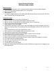
Input and Output Chart (ULTRA-1) J1 connector - black is TIC board ground and white is data wire. J9 connector for liquid crystal display.
41084 102709
Input and Output Chart (ULTRA-2) J1 connector - black is TIC board ground and white is data wire. J2 connector for touch pad/ membrane switch (see touch pad pin out test). J5 connector for liquid crystal display. J12 connector for models with Autofill option.
41084 102709
41084 102709