
User's Manual


Page 6
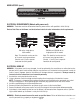
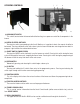
L1, L2, L3, are the 3 phases
V1 = Phase to phase voltage, between any 2 phases.
V2 = Phase to neutral voltage, L1 to neutral must be 120V.
SYSTEM
VOLTAGE V1 V2
208 208 120
240 240 120
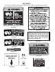
CAUTION: Do not connect L1 to a circuit operating at
more than 150 volts to ground.
200 and 230 volt ac
single phase, 60 Hz models
Note: This electrical service
consists of 2 current carrying
conductors (L1 and L2) and a
separate conductor for earth
ground.
120/208 and 120/240 volt ac
three phase, 50 Hz models
Note: This electrical service
consists of 4 current carrying
conductors (Neutral, L1, L2
and L3) and a separate con-
ductor for earth ground.
ELECTRICAL HOOK-UP
CAUTION – Improper electrical installation will damage electronic components. Damage caused by incorrect
electrical connections is not covered by warranty.
1. An electrician must provide electrical service as specified.
2. Using a voltmeter, check the voltage and color coding of each conductor at the electrical source.
3. Remove the front panel beneath the sprayheads to gain access to the terminal block.
4. Feed the cord through the strain relief and connect it to the terminal block.
5. Connect the brewer to the power source and verify the voltage at the terminal block before proceeding. Re-
place the front panel.
6. If plumbing is to be hooked up later be sure the brewer is disconnected from the power source. If plumbing
has been hooked up, the brewer is ready for Initial Set-Up.
WARNING – Electrical connections must be made as specified above. Failure to follow these instructions can
result in personal injury, property or equipment damage.
ELECTRICAL REQUIREMENTS (Models without power cord)
WARNING - The brewer must be disconnected from the power source until specified in Initial Set-Up.
Refer to Data Plate on the Brewer, and local/national electrical codes to determine circuit requirements.
,2%$
7()4%
'2%%.
.%542!,
,",!#+
,",5%
'2%%.
L2 RED
200 or
230V
GREEN
L1 BLACK
GREEN
35879.1 071405