
Product Manual

INSTALLATION STEPS:
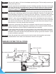
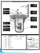
See typical installation diagram in page 4
We recommend that you install your pump and basin in a clean location where there is
adequate room for servicing at a later date. Protection from freezing temperatures and good
ventilation should be considered as well, to provide the pump an environment for long life.
Assuming that you have a sump pit located in your basement oor... Your sump pit should be
constructed from concrete, brick, tile or more recently a sump basin made from plastic and/or
berglass. The minimum size of your sump pit must be 18” in diameter and no less than 25”
deep. When pit is ready, proceed to next step.
Friction losses in the discharge pipe must be taken into consideration when many elbows and
ttings are installed in the discharge line. Each elbows and ttings must be considered as
1 feet of head.
Never run the pump dry. Damage to the seal may occur.
The run of the pipe from the check valve to the existing waste or drain line must never
be slooping downward except when connecting to same.
For a new installation, install your sewage basin in the excavation you have provided in the
basement oor of your home. Connect the necessary piping from your shower trap, toilet, etc.,
to the inlet of your sewage basin, with the proper pipe and ttings.
(See diagram)
Cut a length of 40” to 42” of 2” ABS/DWV pipe. Cement the 1 1/4” male adaptor to 2” slip to one
end of this pipe.
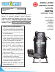
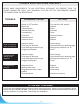
APPLICATIONS:
• Designed for a permanent installation for homes and cottages application.
IMPORTANTE NOTICE:
The following are minimum requirements in order to protect your residence from ooding. It is a small
investment but it is your personal responsibility to protect your home, family and valuables. Failure to
comply with the following requirements will also void your warranty:
- Two (2) pumps have to be installed in the sewage pit. The rst pump as a primary pump and the second
pump as the backup unit.
- An Alarm system model 450454 has to be installed to advise you of any malfunctions.
Pump selection, proper and adequate installation are a must to comply with local by-laws and need to be
adhered to.
STEP 1
STEP 2
STEP 3
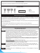
FRICTION LOSS IN
PIPE NOT INCLUDED.
CAPACITIES:
3.0m 7100 10’ 1875
6.0m 6200 20’ 1635
9.0m 4200 30’ 1100
10.5m 1900 35’ 500
HEAD US GPH HEAD LPH
3
• 3/4 HP
• 115 V AC
• 60 Hz
• 7 A (14 A at start)