
Data Sheet
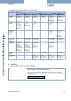
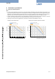
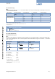
Table Of Contents

Type 3285
8 | 14
Visit product website
5. Performancespecications
5.1. Duty cycle derating diagram
Note:
• For motor valves it is essential to know the duty cycle during operation. Self-heating of the motor limits the maximum duty cycle.
High ambient temperatures amplify the risk of damage due to overheating. The diagram below shows the suggested duty cycles
dependent on the ambient temperature. Running the motor control valve in the power saving mode (lower actuator force) allows
higher duty cycles. The motor is optimized for the valve function regarding dimensions, power consumption and costs.
• The duty cycle does not refer to the duty cycle of the device but to the duty cycle of the motor. This is not switched on unless the
valve is to move. Frequent set-point value changes will drastically increase the duty cycle of the motor.
• Operating the valve beyond the suggested duty cycles leads to a drastically reduced lifetime of the valve.
Derating curve for standard version Derating curve for positioner and process controller
5 10
10
15 20
20
30
40
50
60
70
80
90
100
25 30
35 40 45
50
55 60 65
max. ambient temperature [°C]
Duty cycle [%]
Normal mode
Power saving mode
5 10
10
15 20
20
30
40
50
60
70
80
90
100
25 30
35 40 45
50
55 60 65
max. ambient temperature [°C]
Duty cycle [%]
Normal mode
Power saving mode