
Data Sheet
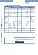
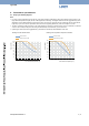
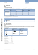
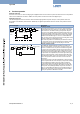
Table Of Contents

Type 3285
9 | 14
Visit product website
5.2. Pressure range
Note:
Please use the product lter of our eShop on the Bürkert website to order from the standard program. Alternatively, the form can be
used at the end of the data sheet.
Valve function Nominal diameter/
Orice
Port connection
1.)
K
VS
-value water Pressure range
3.)
[mm] [m³/h]
2.)
[bar(g)]
Control valve, with-
out safety position in
case of power failure
8 G ½ 1.8 6
10 G ½ 2.5 6
12 G ¾ 3.9 6
15 G ¾ 5.4 6
20 G1 8.1 6
25 G1 9.6 6
1.) Other cable connections (NPT, sub-base) on request
2.) K
VS
-value: Measured with water (20 °C) and 1bar pressure drop over valve
3.) Fuel gases may vary
Further versions on request
Analytical
Oxygen version
Parts oil-, fat- and silicon free
5.3. Flow characteristic
Determination of
the K
V
value
Note:
Once the K
V
-value required for the application has been calculated, it can be compared with the K
VS
-values from the ordering chart.
The K
VS
-value must be higher than the K
V
-value of the application, but should be neither too high nor too close to it - as a recommen-
dation: 10 % higher.
Pressure drop K
V
value for liquids K
V
value for gases
[m
3
/h] [m
3
/h]
Sub-critical
p
2
>
2
p
1
=
Q
ρ
Δp
1000
=
Q
514
Q
N
ρ
N
T
1
Δ p
p
2
Supercritical
p
2
<
2
p
1
=
Q
ρ
Δp
1000
=
QQ
N
ρ
N
T
1
257
p
1
K
V
Flow coecient [m
3
/h]
1.)
Q
N
Standard ow rate [m
N
3
/h]
2.)
p
1
Inlet pressure [bar]
3.)
p
2
Outlet pressure [bar]
3.)
∆p Dierential pressure p
1
…p
2
[bar]
ρ Density [kg/m
3
]
ρ
N
Standard density [kg/m
3
]
T
1
Medium temperature [(273+t)K]
1.) Measured for water, ∆p = 1bar, over the value
2.) At reference conditions 1.013bar and 0 °C (273 K)
3.) Absolute pressure