
Instruction Manual


5
4.2 Application conditions
Ambient temperature: max. +55 °C
Permitted medium temperature and permitted media depending on
seal material:
Seal
material
Medium
temperature
Permitted media
FKM 0 ... +90 °C
Per-solutions, hot oils without additives,
diesel and heating oil without additives,
detergent solution
EPDM -30 ... +90 °C
Oil and grease-free liquids, cold and
hot water
NBR 0 ... +80 °C Cold and warm water, neutral gases
Operating duration: Unless otherwise indicated on the type label,
the solenoid system is suitable for continuous
operation
Important information for functional reliability during continuous
operation: If standstill for a long period at least 1-2 activations
per day are recommended.
Service life: High switching frequency and high pressures
reduce the service life
4.3 Conformity
In accordance with the EC Declaration of conformity, Type 0280 is com-
pliant with the EC Directives.
4.4 Standards
The applied standards, which verify conformity with the EC Directives,
can be found on the EC-Type Examination Certificate and / or the EC
Declaration of Conformity.
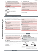
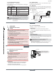
4.5 Type label
Type
Operating
principle
Orifice
Seal material
Body material
Identification
number
Manufacturer code
Voltage, Frequency,
Power consumption
Connection thread, Operating
pressure
0280 A 8,0 NBR MS
Made in Germany
00041346
W17MG
220-230V 50-60 Hz 8W
G1/2 P
N 0.2
- 1
6 bar
english
6
5 INSTALLATION
5.1 Safety instructions
Danger!
Risk of injury from high pressure in the equipment!
▶ Before loosening the pipes and valves, turn off the pressure and
vent the lines.
Risk of injury due to electrical shock!
▶ Before reaching into the device or the equipment, switch off the
power supply and secure to prevent reactivation.
▶ Observe applicable accident prevention and safety regulations for
electrical equipment.
Warning!
Risk of injury from improper installation!
▶ Installation may be carried out by authorized technicians only and
with the appropriate tools.
Risk of injury from unintentional activation of the system and an
uncontrolled restart!
▶ Secure system from unintentional activation.
▶ Following assembly, ensure a controlled restart.
5.2 Before installation
Installation position: any, actuator preferably upwards.
Procedure:
→ Check pipelines for dirt and clean.
→ Install a dirt filter before the valve inlet (≤ 400 µm).
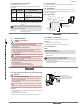
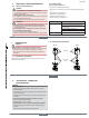
5.3 Installation
note!
Caution risk of breakage!
• Do not use the coil as a lever arm.
→ Hold the device with a open-end wrench on the body and screw
into the pipeline.
Valve body must not be installed under tension.
Sealing material must not get into the device.
→ Observe direction of flow:
The arrow on the body indicates the direction of flow (no function in
opposite flow direction).
english
7
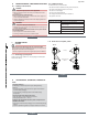
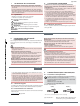
5.4 Electrical connection of the cable plug
Warning!
Risk of injury due to electrical shock!
▶ Before reaching into the system, switch off the power supply and
secure to prevent reactivation.
▶ Observe applicable accident prevention and safety regulations for
electrical equipment.
If the protective conductor is not connected, there is a risk of electric
shock!
▶ Always connect protective conductor and check electrical continuity.
Procedure:
→ Tighten cable plug (for permitted types see data sheet), observing
max. torque 1 Nm.
→ Check that seal is fitted correctly.
→ Connect protective conductor and check electrical continuity.
Authorized cable plug
e.g. Type 2508 or other suitable
cable plug in accordance with
DIN EN 175301-803 Form A
Seal
max. 1 Nm
english
Type 0280