CONTENTS 1. 1.1 1.2 2. 2.1 2.2 2.3 2.4 3. 3.1 3.2 3.3 3.4 3.5 3.6 4. 4.1 4.2 4.3 4.4 4.5 4.6 4.7 4.8 4.9 4.10 4.11 4.12 4.13 4.14 4.15 4.16 4.17 4.18 4.19 4.20 4.21 4.22 4.23 5. 6. 6.1 6.2 6.3 7. 8. 9. 10.
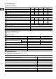
2. Technical data 2.1 Mechanical data 7800-2 7800-8 7800-12 7800-19 Maximum capacity without anti-cavitation *1 [l/h] 2.5 7.5 12 18.5 Maximum capacity with anti-cavitation *1 [l/h] 1.8 5.6 9 14.5 37 Maximum pressure [bar] 18 10 6 6.2 2.6 Maximum stroke rate per minute [stroke/min.] 180 180 180 151 151 Maximum suction lift during operation [m] 7800-48 6 Maximum suction lift when priming with wet valves [m] 1.
3.3 Installation of pump See dimensions at the end of these instructions. All dimensions are in mm. • See also the installation example in section 3.4. • Note: The dosing head may contain water from the factory test. If a liquid which must not come into contact with water is to be dosed, it is recommended to let the pump run with another liquid to remove the water from the dosing head before installation. • Note: Tighten the bolts in the dosing head after 2 to 5 operating hours (torque 5 Nm).
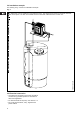
3.4 Installation example The drawing in fig. 2 shows an installation example. Fig. 2 TM01 8421 0204 The 7800 pump can be installed in many different ways. The sketch below shows an example with sidefitted control panel. The tank is a Buerkert chemical tank with a Buerkert level control unit. 3.5 Electrical connection • The electrical connection of the pump should be carried out by qualified persons in accordance with local regulations. • For electrical data of the pump, see section 2.2.
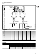
3.6 Connection overview Fig.
4. Functions 4.1 Control panel Fig. 4 LCD display, see section 4.7 ml/h Navigation/ settings, see section 4.7 Navigation/ settings, see section 4.7 Maximum capacity (priming), see section 4.3 Menu, see section 4.7 100% On/off button, see section 4.7 Green indicator light, see section 4.5 Red indicator light, see section 4.5 10 M12 connection pulse/analog input, see section 4.4 M12 connection level control, see section 4.4 Mains connection TM01 8423 0100 Connection alarm relay/bus.
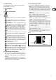
4.2 Start/stop of pump The pump can be started/stopped in two different ways: • Locally on the pump control panel. • By means of an external on/off switch connected to the pulse input. See connection overview in section 3.6. The functions of the indicator lights and the built-in alarm relay appear from the table below: Condition Pump running Green LED Red LED Display On Off Normal indication 4.3 Priming/venting of pump The pump control panel incorporates a 100% button.
4.6 Fieldbus communication The pump can be configured for fieldbus applications. The following bus types are available: Control variant Bus type AP Profibus AG GENIbus Separate instructions are supplied with each bus type.
4.7 Menu The pump features a user-friendly menu which is activated by pressing the button. During start-up, all texts will appear in English language. To select language, see section 4.19. Fig. 5 All menu items are described in the following sections. When appears at a menu item, it means that this item is activated. By selecting “RETURN” anywhere in the menu structure, you will return to the operating display without changes. See section 4.9 See section 4.23 See section 4.10 See section 4.
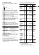
4.8 Operating modes Note: The displayed l and ml values are only reliable if the pump has been calibrated to the actual installation, see section 6. The pump can run in five different operating modes: • Manual • Pulse • Analog • Timer (internal batch control) • Batch (external batch control) See description in the following sections. Fig. 7 Set quantity in ml/pulse 4.9 Manual Set value 4.10 Pulse The pump is dosing according to an external pulse signal, i.e.
Fig. 9 Value according to analog signal If 4-20 mA or 20-4 mA is selected and the signal falls below 2 mA, the pump will indicate a fault. This situation occurs if the connection is interrupted, for instance if the wire is damaged. Change the analog mode as illustrated in fig. 10: Fig.
4.12 Timer Fig. 12 The pump is dosing the set quantity in batches at the maximum capacity or the set maximum capacity, see section 4.15. The time until the first dosing “NX” and the following sequences “IN” can be set in minutes, hours and days. The maximum time limit is 9 days, 23 hours and 59 minutes (9:23:59). The lowest acceptable value is 1 minute. The internal timer continues even if the pump is stopped by means of the on/off button, empty tank or stop signal, see fig. 11.
4.13 Batch Fig. 14 The pump is dosing the set quantity in batches at the maximum capacity or the set maximum capacity, see section 4.15. The quantity is dosed every time the pump receives an external pulse. If the pump receives new pulses before the previous batch is performed, these pulses will be ignored. Fig. 13 Set value per batch Quantity per batch Pulse Pulse TM01 8947 0900 4.14 Anti-cavitation The setting range is the same as for Timer, see section 4.12.
4.15 Capacity limitation This function offers the possibility of reducing the maximum pump capacity (MAX CAP). It influences the functions in which the pump is normally operating at maximum capacity. Under normal operating conditions, the pump cannot operate at a capacity which is higher than the one stated in the display. This does not apply to the maximum capacity button 100% , see section 4.3. Fig. 16 Fig. 17 Total dosed quantity Total number of strokes Set maximum capacity Operating display 4.
4.17 Resetting When “DEFAULT” is activated, the pump will return to the factory settings. Fig. 18 Operating display Note: The calibration is also set back to the default setting. This means that a new calibration is required when the “DEFAULT” function has been used. Operating display without changes 4.18 Return 4.19 Language Fig.
Fig. 20 Operating display Operating display 4.20 Input setup Fig. 21 shows all possible settings. The level and stop inputs can be changed from NO (normally open) to NC (normally closed) function. If changed, the inputs must be short-circuited in normal operation. For the analog input, one of the following signal types can be selected: • 4-20 mA (default), • 20-4 mA, • 0-20 mA, • 20-0 mA. See also section 4.11 Analog. Change the level input to an input for dosing monitoring as illustrated in fig. 21.
4.21 Measuring units It is possible to select metric units (litre/millilitre) or US units (gallons/millilitre). Metric measuring units: • In manual and analog modes, set the quantity to be dosed in litres per hour (l/h) or millilitres per hour (ml/h). • In pulse mode, set the quantity to be dosed in ml/pulse. The actual capacity is indicated in litres per hour (l/h) or millilitres per hour (ml/h). • For calibration, set the quantity to be dosed in ml per 100 strokes.
4.22 Dosing monitoring A dosing monitor is available as an accessory. Separate instructions are supplied with the monitor. Fig. 23 Monitor mounted on the suction side of the pump The dosing monitor is designed to monitor the dosing of liquids which may cause gas accumulation in the dosing head, thus stopping the dosing process even if the pump is still operating.
4.23 Control panel lock It is possible to lock the buttons on the control panel to prevent malfunction of the pump. The locking function can be set to “ON” or “OFF”. The default setting is “OFF”. A PIN code must be entered to change from “OFF” to “ON”. When “ON” is selected for the first time, “_ _ _ _” will appear in the display. If a code has already been entered, it will appear when an attempt to change to “ON” is made. This code can either be re-entered or changed.
5. Start-up Step Action 1 Connect the hoses/pipes: • Connect the suction and dosing tubes/pipes to the pump. • Connect a tube to the vent valve, if required, and lead the hose to the tank. 2 100% 3 Switch on the electricity supply: • The display is on. • The green indicator light is flashing (the pump has stopped). • Select language, if required, see section 4.19. Select the operating mode (see section 4.8): • Manual. • Pulse. • Analog. • Timer. • Batch.
6. Calibration It is important that the pump is calibrated after installation to ensure that the correct value (ml/h or l/h) appears in the display. The calibration can be carried out in three different ways: • Direct calibration (recommended). The dosed quantity of 100 strokes is measured directly. See section 6.1. • Indirect calibration. A calibration factor selected from a table is used for the specific installation. This method can be used if it is not possible to carry out a direct calibration.
6.1 Direct calibration Before calibration, make sure: • that the pump is installed with foot valve, injection valve, etc. in the existing system. • that the pump is running at the counter pressure it is supposed to operate at (adjust the counter pressure valve, if required). • that the pump is operating with the correct suction lift. To carry out a direct calibration, proceed as follows: Action Pump display 1. Prime the dosing head and the suction tubing. 2. Stop the pump. The green LED is flashing. 3.
6.2 Indirect calibration A value from the following table is to be added to the default factory calibration value in the display. To reset the pump to the factory calibration value, activate the “DEFAULT” function, see section 4.17. To use the values, the following must be fulfilled: • The viscosity and density of the liquid to be dosed must not differ considerably from water at 20°C. • A Grundfos installation kit or corresponding foot valve, injection valve and hose diameter must be used.
6.3 Check calibration 7. Maintenance In check calibration, the calibration value is calculated by reading the consumption of chemical in a specific period and comparing this with the number of dosing strokes performed in the same period. This calibration method is very accurate and especially suitable for check calibration after long periods of operation or if direct calibration is impossible. The calibration can for instance be carried out when the chemical tank is replaced or filled.
9. Fault finding chart Fault Cause The dosing has stopped or the output is too low. Valves leaking or blocked. Remedy Check and clean valves. Valves incorrectly installed. Remove and fit valves. Check that the arrow on the valve casing is pointing in the liquid flow direction. Check that all O-rings have been fitted correctly. Suction valve or suction pipe/hose leaking or blocked. Clean and seal the suction pipe/hose. Suction lift too high. Install the pump in a lower position.
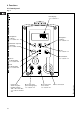
sectional drawing of the dosing head (7800-19 / -48) 15 14 13 2 18 4 5 3 6 7 8 9 11 12 30 TM01 9976 3500 10
assembly / disassembly of dosing head and valves 31
dimensions: 130 B 110 TM01 9232 0900 100% C 160 D ml/h 98 50 7800-2 7800-8 A 7800-12 7800-19 7800-48 A = [mm] 137 192 B = [mm] 239 294 C = [mm] 36 15 D = [mm] 168 188 32
Please copy, fill in and sign this sheet and attach it to the pump returned for service We hereby declare that this product: Product type:____________________________ Product number:_________________________ is free from hazardous chemicals, biological and radioactive substances _________________ Date and signature _________________ Company stamp 60