Types 8025 / 8035 Flowmeter Durchflussmessgerät Débitmètre Operating Instructions Bedienungsanleitung Manuel d‘utilisation
We reserve the right to make technical changes without notice. Technische Änderungen vorbehalten. Sous réserve de modifications techniques.
Type 8025 / 8035 1. About this manual............................................................................................................................................................................................. 6 1.1. Symbols used................................................................................................................................................................................................ 6 1.2. Definition of the word "device"............................
Type 8025 / 8035 8. Wiring...........................................................................................................................................................................................................................27 8.1. Making the installation equipotential..............................................................................................................................................27 8.2.
Type 8025 / 8035 9.7. 10. 9.6.7. Configuring the filter of the measured flow rate................................................................................................. 55 9.6.8. Resetting both totalizers........................................................................................................................................... 55 Details of the Test menu..........................................................................................................................
Type 8025 / 8035 About this manual 1. About this manual This manual describes the entire life cycle of the device. Please keep this manual in a safe place, accessible to all users and any new owners. This manual contains important safety information. Failure to comply with these instructions can lead to hazardous situations. • This manual must be read and understood. 1.1. Symbols used danger Warns against an imminent danger. • Failure to observe this warning can result in death or in serious injury.
Type 8025 / 8035 Intended use 2. Intended use Use of the device that does not comply with the instructions could present risks to people, nearby installations and the environment. • The compact version of the flowmeter type 8025 or 8035 is designed to measure the flow rate of a liquid and to totalise the volume of a liquid. • The remote version of the flowmeter type 8025 is a transmitter that must be connected to an 8020 or an 8030 flow sensor with a sinus or a pulse output, only in "Low Power" version.
Type 8025 / 8035 Basic safety information 3. Basic safety information This safety information does not take into account: • any contingencies or occurences that may arise during installation, use and maintenance of the devices. • the local safety regulations for which the operating company is responsible including the staff in charge of installation and maintenance. Danger due to electrical voltage.
Type 8025 / 8035 General information 4. General information 4.1. Manufacturer's address and international contacts To contact the manufacturer of the device, use following address: Bürkert SAS Rue du Giessen BP 21 F-67220 TRIEMBACH-AU-VAL You may also contact your local Bürkert sales office. The addresses of our international sales offices are available on the internet at: www.burkert.com 4.2.
Type 8025 / 8035 Description 5. Description 5.1. Area of application The compact version of the flowmeter type 8025 or 8035 is designed to measure the flow rate of a liquid and to totalise the volume of a liquid. The remote version of the flowmeter type 8025 is a transmitter that must be connected to an 8020 or an 8030 flow sensor with a sinus or a pulse output, only in "Low Power" version. 5.2. General description The 8025 is a flowmeter available in compact, panel or wall-mounted version.
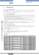
Type 8025 / 8035 Description Supply voltage Seals Electrical connection Relays Sensor Order code 115/230 V AC FKM 1) Coil, short 418425 115/230 V AC FKM Terminal strips via 2 cable glands - 1) - Coil, long 418426 115/230 V AC FKM 1) 2 Hall, short 418431 115/230 V AC FKM 1) Terminal strips via 2 cable glands 2 Hall, long 418432 115/230 V AC FKM 2 Coil, short 418433 115/230 V AC FKM 1) Terminal strips via 2 cable glands 2 Coil, long 418434 1) 1) Delivered with the d
Type 8025 / 8035 Description Supply voltage Electrical connection Relays Sensor 12-36 V DC Terminal strips via 2 cable glands Terminal strips via 2 cable glands - Coil UR and CSA recognized no 2 Hall no Terminal strips via 2 cable glands Terminal strips via 2 cable glands Terminal strips via 2 cable glands 2 Coil no - Hall no 2 Hall no 12-36 V DC 12-36 V DC 115/230 V AC 115/230 V AC 2) identified by the logo yes Order code 423916 444007 2) 553433 423918 423922 423924 located on
Type 8025 / 8035 Technical data 6. Technical data The following technical data are relevant for an 8025 compact or an 8035 flowmeter and for the remote 8025 flowmeter connected to a Bürkert flow sensor 8020 / 8030 in a "Low Power" version only. 6.1.
Type 8025 / 8035 Technical data 6.3. General data Pipe diameter • DN20 (except for the DN specified p.22) to DN400 • 8025 flowmeter • 8025 transmitter (remote versions) • DN06 to DN400 • 8035 flowmeter Type of fitting • DN06 to DN65 • S020, for a compact 8025 Type of fluid • S030, for a 8035 • liquid • viscosity: max. 300 cSt Fluid temperature (compact versions) • rate of solid particles: max.
Type 8025 / 8035 Technical data A P (bar) 11 10 9 Metal PVDF 8 PVDF (PN10) PVC + PP 7 6 5 4 PVC (PN10) 3 2 1 0 PP (PN10) -15 0 +20 +40 +80 T (°C) +60 A: range of use Fig. 2: Fluid temperature /pressure dependency curves for the 8025 compact version, depending on the material the S020 fitting is made of P (bar) 16 15 14 13 12 11 10 9 8 7 6 5 4 3 2 1 0 -30 A A Metal PVDF PVDF (PN10) PVC + PP PVC (PN10) PP (PN10) -10 +10 +30 +50 +70 +90 +110 T °C A: range of use Fig. 3: 6.4.
Type 8025 / 8035 Technical data Part Housing Material • 8025, compact or panel versions • PC • 8025, wall-mounted versions • ABS • 8035 Cover • PC • 8025 compact versions or 8035 • PC (Cover with lid) • 8025 panel versions • PC • 8025, wall-mounted versions Front foil Screws (4) Male fixed connector and female connector (type 2508) Cable glands • ABS Polyester Stainless steel PA PA R 90 91 88 (21) 85.5 (30) 164.50 203 88 82 Fig.
Type 8025 / 8035 Technical data Dimensions of 8025 compact flowmeter associated to an S020 fitting [height H in mm] H Tab.
Type 8025 / 8035 Technical data 31.50 143 90 120 126 23 23 Fig. 6: Dimensions [mm] of the electronic module of the 8025 flowmeter in a wall-mounted version Tab. 2: Dimension H [mm] of the 8035 depending on the DN of the S030 sensor-fitting H with S030 sensor-fitting 06 08 15 20 25 32 40 50 65 134 134 139 137 137 140 144 151 151 H DN 88 21 91 180 88 Fig.
Type 8025 / 8035 Technical data 6.5. Electrical data 12-36 V DC power supply • filtered and regulated • SELV circuit (safety extra low voltage), with a safe energy level Power source (not supplied) • oscillation rate: ±10 % • limited power source according to paragraph 9.3 of EN 61010-1 standard • or class 2 source according to UL 1310/1585 and EN 60950-1 standards 115/230 V AC power supply • frequency • 50/60 Hz • supplied voltage • 27 V DC, regulated • current • max.
Type 8025 / 8035 Technical data 6.6. Specifications of the connected flow sensor Sensor input • signal frequency • 2,5 to 400 Hz • pulse signal (Hall) • NPN, open collector • sinus signal (coil) Sensor output • typical sensitivity of 35 mV peak-peak, at 252 Hz • power supply • 10-34 V DC (V+ minus 2 V DC), 1 mA max. 6.7.
Type 8025 / 8035 Installation 7. Installation 7.1. Safety instructions danger Risk of injury due to electrical voltage. • Shut down the electrical power source of all the conductors and isolate it before carrying out work on the system. • Observe all applicable accident protection and safety regulations for electrical equipment. Warning Risk of injury due to nonconforming installation.
Type 8025 / 8035 Installation 7.2. Installation of a compact version 7.2.1. Instructions for installing a compact version onto the pipe The 8025 flowmeter has to be inserted into an S020 fitting mounted on a pipe. The 8035 flowmeter has to be installed on the pipe using the S030 sensor-fitting. →→Choose an S020 or S030 fitting appropriate to the velocity of the fluid inside the pipe: refer to the graphs below: Tab.
Type 8025 / 8035 Installation →→Install the device on the pipe in such a way that the upstream and downstream distances are respected according to the design of the pipes, refer to standard EN ISO 5167-1 and "Fig. 8". flow direction 50 x DN 5 x DN With control valve 25 x DN 5 x DN Pipe with 2 elbows at 90° 18 x DN 5 x DN With pipe expansion Fig.
Type 8025 / 8035 Installation 7.2.2. Installation of the 8025 on the S020 fitting →→Install the S020 fitting onto the pipe obeying the instructions in chap. “7.2.1”. →→Check that there is a seal on the fitting and that it is not damaged. Replace the seal if necessary. 6 1 2 3 4 →→Insert the nut 3 on the fitting 5. →→Insert the snap ring 2 into the groove 4. →→Check that the seal 6 is correctly inserted on the flow sensor. →→Insert the device 1 into the fitting.
Type 8025 / 8035 Installation 7.3. Installation of a panel version of the 8025 flowmeter Install the panel version of the device in a cabinet with a protection class at least IP54 to ensure a degree of pollution 2 inside the cabinet. →→To cut the opening in the cabinet door, use the supplied cutting plan of the frontage of the electrical cabinet, respecting the dimensions indicated in "Fig. 13". 95 80 76 50 95 80 76 50 Fig.
Type 8025 / 8035 Installation 7.4. Installation of a wall-mounted version of the 8025 transmitter NOTE Risk of material damage if the cable glands are not tightly screwed on the housing • Before installing the wall-mounted housing on its support, tighten the nuts of the entry item of the cables glands at a torque of 1.5 Nm. The flow transmitter in a wall-mounted version has 4 holes in the bottom of the housing. →→Remove the blanking strips covering the screws. FLOW Blanking strips ENTER 0....
Type 8025 / 8035 Wiring 8. Wiring danger Risk of injury due to electrical voltage. • Shut down the electrical power source of all the conductors and isolate it before carrying out work on the system. • Observe all applicable accident protection and safety regulations for electrical equipment. Insert the supplied stopper gaskets into the unused cable glands of a wall-mounted or a compact version to ensure the tightness of the device. Only move the selectors when the power supply is off.
Type 8025 / 8035 Wiring 12-36 V DC + - Power supply (*) Metal pipes 12-36 V DC + - Valve, pump,... (or earth rings, not provided, inserted into the pipe) (*) Power supply Plastic pipes *) If a direct earth connection is not possible, fit a 100 nF / 50 V capacitor between the negative power supply terminal and the earth. Fig.
Type 8025 / 8035 Wiring 8.2. Wiring the 8025 compact version and the 8035 with a 4 pin male fixed connector 1: V+ (12-36 V DC) 3 2: Positive pulse output 1 3: L- ( 0 V DC) 2 : Negative pulse output Fig. 18: Pin assignment of the 4 pin male fixed connector →→Unscrew the nut 1 of the cable gland. →→Remove the terminal block 3 from the housing 2. →→Insert the cable through the nut 1 then through the gasket 2 4, through the cable gland and finally through the housing 2.
Type 8025 / 8035 Wiring →→Wire the transistor output using one of the wiring plans of "Fig. 21".
Type 8025 / 8035 Wiring Tab. 5: Positioning of the Source / Sink selector depending on the wiring of the current output of a version with relays Wiring the 4-20 mA output Position of the Source/Sink selector on a version with relays Not wired (jumper wire in place) Sourcing mode Sinking mode 8.3.3. SOURCE SOURCE SINK 115/230 V AC selector The 115/230 V AC selector makes it possible to configure the supply voltage of the device in a 115/230 V AC version.
Type 8025 / 8035 Wiring 8.4.2. Wiring of the relays (versions with relay output) P+ P+ L- L- P- P- L+ L+ Without With PE PE Relays SOURCE SINK Iout NC • 1: relay 1 connection Supply 12..36Vdc • 2: relay 2 connection PE • 3: fixation slots PULSE OUTPUT →→Always secure the relays connection cables in the slots FLOW SENSOR COIL NPN marked 3 (see "Fig. 25"). + - 2 + - 1 Load 1 Load 2 3 Fig. 26: Wiring of the relays 8.4.3.
Type 8025 / 8035 Wiring Wiring of the pulse output in NPN mode Wiring of the pulse output in PNP mode Power supply Power supply 12-36 V DC + - + 5-36 V DC - 300 mA 12-36 V DC + - PLC + (*) + 5-36 V DC - 300 mA PLC + (*) - P+ P+ L- L- P- P- L+ L+ FLOW SENSOR 8025: NPN COIL PE PULSE OUTPUT Supply 12..36Vdc P- P- PE PE Relays Without With Iout NC P+ P+ PE PULSE OUTPUT P+ Supply 12..
Type 8025 / 8035 Wiring Wiring of the current output in sourcing mode 4-20mA input at external instrument 300 mA + - Wiring of the current output in sinking mode 4-20mA input at external instrument Power supply Power supply 300 mA + - + - + - 12-36 V DC 12-36 V DC (*) (*) P+ P+ L- L- Supply 12..36Vdc P- P- Without With L+ L+ SOURCE SINK PULSE OUTPUT PE PE Source/Sink selector (see chap. "8.3.2") PE Relays P+ P+ L- L- Supply 12..
Type 8025 / 8035 Wiring 8.4.5. Wiring the 8025 compact version and the 8035, 115/230 V AC, without relays, with cable glands →→Before wiring the device, configure the selector on the electronic board (see chap. "8.3"). Terminal block 1 The red wire is wired on the NC terminal to make the wiring of the 4-20 mA output easier (see "Fig. 34"). The jumper wire 4 between L+ and NC energizes the NC terminal.
Type 8025 / 8035 Wiring Wiring of the pulse output in NPN mode Wiring of the pulse output in PNP mode + 5-36 V DC - + 5-36 V DC - 8025: PNP FLOW SENSOR COIL NPN P+ P+ PE PULSE OUTPUT Supply 12..36Vdc P+ L- L- P- P- L+ L+ Without With P- P- 8025: NPN Relays P+ P+ PE PULSE OUTPUT PE PE - Iout NC - P+ L- L- P- P- L+ L+ PE PE Relays + 230V Supply 12..
Type 8025 / 8035 Wiring 4-20mA input at external instrument Supply 12..36Vdc P+ P+ L- L- P- P- L+ L+ PE PE Iout NC Without With PE 230V Relays + SOURCE SINK PULSE OUTPUT FLOW SENSOR COIL NPN T 125 mA PE { L N 115/230 V AC power supply If the current output is wired, remove the jumper wire between the terminals Iout and L+. Fig.
Type 8025 / 8035 Wiring Wiring of the pulse output in PNP mode Wiring of the pulse output in NPN mode Supply 12..36Vdc 8025: PNP FLOW SENSOR COIL NPN P+ P+ PLC PE PULSE OUTPUT P+ L- L- P- P- L+ L+ Without With P- P- 8025: NPN SOURCE SINK PE PE PE PULSE OUTPUT Supply 12..
Type 8025 / 8035 Wiring Terminal block 1 2 1 NC: not connected L+: positive power supply P- P- Supply 12..
Type 8025 / 8035 Wiring →→Insert the cable clips: see "Fig. 25". The wiring of the current output and the pulse output of the panel or wall-mounted transmitter, 12-36 V DC, without relays, are the same as for a compact flowmeter, 12-36 V DC, with relays, with cable glands. →→Wire the current output according to "Fig. 31" of chap. "8.4.4". →→Wire the pulse output according to "Fig. 32" of chap. "8.4.4". 8.7. Wiring the 8025, wall-mounted version, 115/230 V AC, with or without relays 8.7.1.
Type 8025 / 8035 Wiring 8.7.2. Wiring the 8025, wall-mounted version, 115/230 V AC, without relays →→Before wiring the device, obey the instructions of chap. "8.7.1".
Type 8025 / 8035 3 4 PE T 250 mA L- L- P+ P+ FLOW SENSOR COIL NPN REL1 2 NPN SENSOR 1 PULSE INPUT 2 3 + SUPPLY 4 NC REL2 1 P- P- L+ L+ PE PE Relays COIL SENSOR 1 2 3 NC 4 NC PE PULSE OUTPUT Supply 12..
Type 8025 / 8035 2 3 4 PE NPN P+ P+ L- L- P- P- L+ L+ T 250 mA FLOW SENSOR COIL REL1 1 PE PULSE OUTPUT NPN SENSOR 1 PULSE INPUT 2 3 + SUPPLY 4 NC REL2 COIL SENSOR 1 2 3 NC 4 NC PE PE Relays Supply 12..36Vdc 230V Without With Iout NC Wiring L N { FLOW SENSOR 5 6 7 8 9 10 + 5-36 V DC + - Fig.
Type 8025 / 8035 Wiring 8.7.3. Wiring the 8025, wall-mounted version, 115/230 V AC, with relays →→Before wiring the device, obey the instructions of chap. "8.7.1".
Type 8025 / 8035 2 3 4 PE T 250 mA FLOW SENSOR COIL 3A/230VAC NPN REL1 1 PE PULSE OUTPUT NPN SENSOR 1 PULSE INPUT 2 3 + SUPPLY 4 NC REL2 COIL SENSOR 1 2 3 NC 4 NC P+ P+ L- L- Supply 12..
Type 8025 / 8035 operating and commissioning 9. operating and commissioning 9.1. Safety instructions Warning Risk of injury due to nonconforming operating. Non-conforming operating could lead to injuries and damage the device and its surroundings. • The operators in charge of operating must have read and understood the contents of this manual. • In particular, observe the safety recommendations and intended use. • The device/installation must only be operated by suitably trained staff.
Type 8025 / 8035 operating and commissioning Process level Configuration level 12.6 L/MIN. >5s ENTER 16.45 ma 0......9 0......9 Parameters Menu 87654 l ENTER Test Menu LANGUAGE offset unit span >5s 231 l. K-FACTOR 0......9 Current + >2s To reset the daily totalizer (identified by a dot after the volume units). 0......9 0......9 frequenc flow PULSE END Relay FILTER total END Process level Fig.
Type 8025 / 8035 operating and commissioning 9.3. Description of the navigation keys and the status LEDs • Selecting the displayed parameter • Confirming the settings • Scrolling up the parameters • Incrementing the figure selected LED indicating the status of the relay 2 (LED ON = contact closed) • Scrolling through the parameters LED indicating the status of the relay 1 • Selecting the figure on the left (LED ON = contact closed) Fig. 52: Description of the display 9.4.
Type 8025 / 8035 operating and commissioning 9.5. Details of the Process level This level is active by default when the device is energized. 12.6 L/MIN. Value of the measured flow rate, displayed in the unit chosen in the "UNIT" parameter of the Parameters menu. 16.45 ma Value of the current output, proportional to the measured flow rate. 87654 l Value of the main totalizer, volume of fluid counted by the device since the last reset. 0......9 231 l.
Type 8025 / 8035 operating and commissioning 9.6.1. Choosing the display language When the device is energized for the first time, the display language is English. LANGuAge English 0......9 deutsch →→The chosen language is active as soon as the ENTER key is pressed français italiano unit Fig.
Type 8025 / 8035 operating and commissioning unit Flow rate →→Choose the flow rate unit. →→Confirm. lit/sec lit/min lit/h m3/min m3/h 0......9 ENTER us gal/s DEC PT 3 us gal/m 0......9 0......9 DEC PT 2 →→Choose the number DEC PT 1 →→Confirm. us gal/h of decimal positions. imp ga/s DEC PT 0 imp ga/m ENTER GA/H If the chosen unit is in litres, m3 or in gallons. total litre m3 0......9 US GAL →→Choose the totalizer unit. →→Confirm. ENTER IMP GAL K-FACTOR Fig.
Type 8025 / 8035 operating and commissioning 9.6.3. Entering the K factor of the fitting used The device determines the flow rate in the pipe using the fitting K factor. The K factor of the fitting used can be entered here. The device may also determine the K factor using a teach-in procedure: see "Fig. 58". The K factor of the fitting used is in the operating instructions of the fitting.
Type 8025 / 8035 operating and commissioning 9.6.4. Configuring the current output The 4-20 mA output provides an electrical current, the value of which reflects the flow rate measured by the device. Example of relation between the measuring range and the current output: mA 20 4 20 180 l/min →→To invert the output signal, give a lower flow rate value to the 20 mA current value than to the 4 mA current value. →→To disable the current output, set both range bounds, 4 and 20 mA, to zero.
Type 8025 / 8035 operating and commissioning 9.6.6. Configuring the relays This parameter makes it possible to set the switching thresholds and the operating behaviour, inverted or not, of each relay. Enter values such as 1- ≤ 1+ and/or 2- ≤ 2+. Both relays work in an hysteresis operating. Relay ENTER 1-= 0000 →→Enter a flow rate value, associated to the low threshold of relays 1, in the unit chosen in the "UNIT" parameter. 0......9 →→Confirm. ENTER 1-= 0008 1+ = 0000 0......9 ENTER inv no 0..
Type 8025 / 8035 operating and commissioning Sense of operation not inverted Contact Sense of operation inverted Contact Inverted NO Inverted YES OFF OFF ON ON 1- (2-) 1+ (2+) 1- (2-) 1+ (2+) Flow rate Flow rate Fig. 62: Hysteresis operating 9.6.7. Configuring the filter of the measured flow rate This parameter makes it possible to dampen the fluctuations: • of the display; • of the current output. Ten filters are available.
Type 8025 / 8035 operating and commissioning The daily totalizer can be reset from the Process level. See chap. "9.4". →→If you do not want to adjust another parameter, go to the "END" parameter of the Parameters menu and press ENTER to save the settings and go back to the Process level. 9.7. Details of the Test menu ENTER To access the Test menu, simultaneously press keys 0......9 for at least 5 s.
Type 8025 / 8035 operating and commissioning 9.7.2. Adjusting the SPAN of the current output This parameter makes it possible to adjust the 20 mA current value transmitted on the 4-20 mA output. →→Connect a multimeter into the measurement loop. ENTER span SP= 20.00 →→The device generates a 20 mA current. →→Measure the current given on the 4-20 mA output using a multimeter. 0......9 frequenc ENTER SP= 19.90 →→Enter the value displayed by the multimeter. The permitted span range is 15 to 21,50 mA.
Type 8025 / 8035 Maintenance and troubleshooting 10. Maintenance and troubleshooting 10.1. Safety instructions danger Danger due to electrical voltage. • Shut down the electrical power source of all the conductors and isolate it before carrying out work on the system. • Observe all applicable accident protection and safety regulations for electrical equipment. Risk of injury due to high pressure in the installation.
Type 8025 / 8035 Maintenance and troubleshooting Message displayed ERROR 7 PWR FAIL Possible cause Recommended action Memory read error: the user settings and the totalizer values are lost. →→Press the ENTER key to acknowledge the error: the totalizers are The supply voltage is too low. • The voltage at the device terminals is lower than 12 V. PU H LIM PU L LIM • The impedance of the current measurement loop is too high (see chap. "6.5").
Type 8025 / 8035 Spare parts and accessories 11. Spare parts and accessories attention Risk of injury and/or damage caused by the use of unsuitable parts. Incorrect accessories and unsuitable replacement parts may cause injuries and damage the device and the surrounding area. • Use only original accessories and original replacement parts from Bürkert. The defective electronic board or housing of your device can be replaced. • Contact the local Bürkert office. 11.1.
Type 8025 / 8035 Spare parts and accessories Position Fig. 70 Designation 5+6+7 Order code Set including: • 2 M20*1.5 / NPT1/2'' reductions (with mounted seals) 551782 • 2 neopren flat seals for the screw plug • 2 M20*1.5 screw plugs Set including: 8+9+14 • 1 M20*1.5 cable gland stopper gasket • 1 2*6 mm multi-way seal for a cable gland 551775 • 1 black EPDM seal for the flow sensor 10 + 2 11 12 13 14 15 16 11.2.
Type 8025 / 8035 Spare parts and accessories Position Fig. 71 Designation 5+6+7 Set including: Order code • 2 M20*1.5 / NPT1/2'' reductions (with mounted seals) 551782 • 2 neopren flat seals for the screw plug • 2 M20*1.5 screw plugs Set including: 8+9 • 1 M20*1.5 cable gland stopper gasket • 1 2*6 mm multi-way seal for a cable gland 551775 • 1 black EPDM seal • 1 mounting instruction sheet Housing with female connector type 2508, coil function Housing for 2 M20*1.
Type 8025 / 8035 Spare parts and accessories 12. Packaging, Transport note Damage due to transport Transport may damage an insufficiently protected device. • Transport the device in shock-resistant packaging and away from humidity and dirt. • Do not expose the device to temperatures that may exceed the admissible storage temperature range. • Protect the electrical interfaces using protective plugs. 13. Storage note Poor storage can damage the device. • Store the device in a dry place away from dust.
Type 8025 / 8035 Spare parts and accessories 64 English
www.burkert.