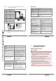
Type 8030 INLINE Flowmeter We reserve the right to make technical changes without notice. Technische Änderungen vorbehalten. Sous réserve de modification technique. www.burkert.com Operating Instructions © 2012 Bürkert SAS Bedienungsanleitung Manuel d'utilisation Operating Instructions 1209/0_EU-ml_00419743 About this manual............................................................3 1. 2. Intended use...........................................................................5 3.
attention Warns against a possible risk. • Failure to observe this warning can result in substantial or minor injuries. note Warns against material damage. • Failure to observe this warning may result in damage to the device or system. Indicates additional information, advice or important recommendations. refers to information contained in this manual or in other documents. →→Indicates a procedure to be carried out.
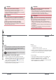
4. note The device may be damaged by the fluid in contact with. • Systematically check the chemical compatibility of the component materials of the device and the fluids likely to come into contact with it (for example: alcohols, strong or concentrated acids, aldehydes, alkaline compounds, esters, aliphatic compounds, ketones, halogenated aromatics or hydrocarbons, oxidants and chlorinated agents). note 5.
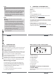
Hall 12-36 V DC Hall Low Power 2 transistors, NPN and PNP energized via the 1 NPN Bürkert transmitter transistor the flow sensor is connected to Order code Output Supply voltage Version of electronic module SE30 6. 423913 423914 Ordering codes of fitting S030 can be found within the related data sheet: refer to the data sheet to select the fitting appropriate to the process.
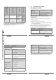
DN H with fitting S030 95,5 95,5 100,5 98 98 102 105,5 112 112 66 40 54 Dimensions [mm] of the SE30 electronic module • Hall version • 12-36 V DC, filtered and regulated • Hall Low Power version Dielectric strength Current consumption • 12-36 V DC, via transmitter the device is connected to 2300 VAC • Hall version • 30 mA max. • Hall Low Power version Protection against polarity reversal • 0,8 mA max.
danger Risk of injury due to electrical voltage. • Shut down and isolate the electrical power source before carrying out work on the system. • Observe all applicable accident protection and safety regulations for electrical equipment. Warning Risk of injury if the fluid pressure/ temperature dependency is not respected. • Take the fluid pressure / temperature dependency into account according to the material of the fitting (see the operating instructions of the fitting used).
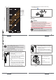
→→Assemble the electronic module and the fitting gpm m3/h 1000 l/min 200 3000 500 2000 100 200 100 50 flow rate 20 10 5 2 1 0.5 0.2 0.1 0.05 24 1000 according to Fig. 2. DN65 50 500 20 200 DN15 (DN15 or DN20)* 5 Fig. 2: 50 20 10 2 DN08 1 DN06 0.5 0.2 1 Wiring danger 0.1 0.05 0.5 Protect the power supply 0.02 0.
Pulse input on external instrument - + 1: V+ (12-36 V DC) Terminal block of the 2508 1 2: NPN transistor output V+ 3: 0 V DC 3 - + 12-36 V DC Power supply Fig. 5: 4: not connected 2 0 V DC Fig. 7: NPN wiring of the Hall version Pin assignment of the fixed connector, Hall Low Power version 1 Terminal block of the 2508 - + 1 V+ 3 - + 12-36 V DC Fig. 6: 28 8.
. 10. Packaging, transport Accessories Attention attention Risk of injury and/or damage caused by the use of unsuitable parts. Incorrect accessories and unsuitable spare parts may cause injuries and damage the device and the surrounding area. • Use only original accessories and original spare parts from Bürkert.
Typ 8030 INLINE Durchfluss-Messgerät We reserve the right to make technical changes without notice. Technische Änderungen vorbehalten. Sous réserve de modification technique. Bedienungsanleitung www.burkert.com © 2012 Bürkert SAS Deutsch Operating Instructions 1209/0_EU-ml_00419743 Die Bedienungsanleitung..........................................3 1. 2. Bestimmungsgemässe Verwendung................5 3. Grundlegende Sicherheitshinweise...............6 4. Allgemeine Hinweise.....................
2. VORSICHT! Warnt vor einer möglichen Gefährdung! • Nichtbeachtung kann mittelschwere oder leichte Verletzungen zur Folge haben. Hinweis! Warnt vor Sachschäden! • Bei Nichtbeachtung kann das Gerät oder die Anlage beschädigt werden. bezeichnet wichtige Zusatzinformationen, Tipps und Empfehlungen. verweist auf Informationen in dieser Bedienungsanleitung oder in anderen Dokumentationen. →→markiert einen Arbeitsschritt, den Sie ausführen müssen.
4. Hinweis! Das Gerät kann durch das Medium beschädigt werden. • Kontrollieren Sie systematisch die chemische Verträglichkeit der Werkstoffe, aus denen das Gerät besteht, und der Flüssigkeiten, die mit diesem in Berührung kommen können (zum Beispiel: Alkohole, starke oder konzentrierte Säuren, Aldehyde, Basen, Ester, aliphatische Verbindungen, Ketone, aromatische oder halogenierte Kohlenwasserstoffe, Oxidations- und chlorhaltige Mittel).
Verfügbare Versionen des Elektronikmoduls SE30 6. Betriebsbedingungen Hall Low Power 2 TransistorAusgänge, NPN und PNP über den ange- 1 NPNschlossenen TransistorBürkert-Transmitter Ausgang Bestellnummer Ausgang Betriebsspannung Version des Elektronikmoduls SE30 Alle Versionen des Elektronikmoduls werden über einen Gerätestecker elektrisch angeschlossen.
DN H mit Fitting S030 95,5 95,5 100,5 98 98 102 105,5 112 112 66 40 9 54 Abmessungen [mm] des Elektronikmoduls SE30 16 Werkstoff PC PA / Edelstahl / NBR Siehe die Bedienungsanleitung des verwendeten Fittings. • Hall-Version • 12-36 V DC, gefiltert und geregelt • Hall Low Power-Version • 12-36 V DC, über angeschlossenen Transmitter 2300 VAC Spannungsfestigkeit Stromaufnahme • Hall-Version • max. 30 mA • Hall Low Power-Version Schutz gegen Verpolung Schutz vor Spannungsspitzen • max.
Warnung! Gefahr! Verletzungsgefahr durch Stromschlag! • Schalten Sie vor Beginn der Arbeiten in jedem Fall die Spannung ab, und sichern Sie diese vor Wiedereinschalten! • Beachten Sie geltende Unfallverhütungs- und Sicherheitsbestimmungen für elektrische Geräte! Verletzungsgefahr durch Nichteinhalten der DruckTemperatur-Abhängigkeit der Flüssigkeit. • Je nach Art der Werkstoffe des Fittings (siehe die Bedienungsanleitung des verwendeten Fittings) die Druck-Temperatur-Abhängigkeit der Flüssigkeit beachten.
→→Das Elektronikmodul gemäß Bild 2 auf das Fitting gpm m3/h 1000 l/min 200 3000 500 2000 100 200 100 50 Durchfluss 20 10 5 2 1 0.5 0.2 0.1 0.05 1000 montieren. DN65 50 500 20 200 DN15 (DN15 oder DN20)* 5 Bild 2: 50 20 10 2 DN08 1 DN06 0.5 0.2 1 0.1 0.05 0.5 Verkabelung Gefahr! 0.02 0.
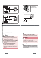
Pulseingang am externen Instrument - + 1: V+ (12-36 V DC) Klemmleiste des 2508 1 2: NPN-Transistorausgang V+ 3: 0 V DC 3 - + 12-36 V DC Versorgungsspannung Bild 5: 4: nicht belegt 2 0 V DC Bild 7: Anschluss als NPN der Hall-Version Belegung des Gerätesteckers der Hall Low Power-Version 1 Klemmleiste des 2508 - + 1 V+ 3 - + 12-36 V DC Bild 6: Versorgungsspannung Anschluss als PNP der Hall-Version Wartung Sicherheitshinweise Gefahr! Verletzungsgefahr durch Stromschlag! • Schalten Sie vor
9. 10. verpackung, Transport Zubehör VORSICHT! VORSICHT! Verletzungsgefahr, Sachschäden durch ungeeignete Teile! Falsches Zubehör und ungeeignete Ersatzteile können Verletzungen und Schäden am Gerät und dessen Umgebung verursachen. • Verwenden Sie nur Originalzubehör sowie Originalersatzteile der Fa. Bürkert.
Type 8030 Débitmètre INLINE We reserve the right to make technical changes without notice. Technische Änderungen vorbehalten. Sous réserve de modification technique. Manuel d'utilisation www.burkert.com © 2012 Bürkert SAS Français Operating Instructions 1209/0_EU-ml_00419743 À propos de ce manuel.................................................3 1. 2. Utilisation conforme....................................................5 3. Consignes de sécurité de base...........................
2. attention Met en garde contre un risque éventuel. • Son non-respect peut entraîner des blessures légères ou de gravité moyenne. remarque Met en garde contre des dommages matériels. • Son non-respect peut entraîner des dommages sur l'appareil ou l'installation. désigne des informations supplémentaires, des conseils ou des recommandations importants. renvoie à des informations contenues dans ce manuel ou dans d'autres documents. →→indique une opération à effectuer.
4. remarque L'appareil peut être endommagé par le fluide en contact. • Vérifier systématiquement la compatibilité chimique des matériaux composant l’appareil et les produits susceptibles d’entrer en contact avec celui-ci (par exemple : alcools, acides forts ou concentrés, aldéhydes, bases, esters, composés aliphatiques, cétones, aromatiques ou hydrocarbures halogénés, oxydants et agents chlorés). remarque 5.
Toutes les versions du module électronique se raccordent via une embase électrique mâle. Conditions d‘utilisation Hall Hall Low Power alimenté par le transmetteur Bürkert raccordé à l'appareil Sortie Tension d'alimentation 12-36 V DC Référence de commande 6. Version du module électronique SE30 Versions disponibles du module électronique SE30 2 transistors, NPN et PNP 1 transistor NPN 423913 423914 français Type de fluide Fluide groupe 2 § 1.3.
DN H avec raccord S030 95,5 95,5 100,5 98 98 102 105,5 112 112 66 40 9 54 • version Hall • 12-36 V DC, filtrée et régulée • version Hall Low Power Tenue de rigidité diélectrique Consommation propre • 12-36 V DC, par le transmetteur raccordé à l'appareil 2300 VAC • version Hall • 30 mA max. • version Hall Low Power Protection contre les inversions de polarité • 0,8 mA max. oui français français 16 oui 7. oui Consignes de sécurité impulsion, NPN et PNP, collecteur ouvert, 100 mA max.
Avertissement danger Risque de blessure par décharge électrique. • Couper et consigner l'alimentation électrique avant d'intervenir sur l'installation. • Respecter la réglementation en vigueur en matière de prévention des accidents et de sécurité relative aux appareils électriques. Avertissement Avertissement Risque de blessure dû à une installation non conforme. • L'installation électrique et fluidique ne peut être effectuée que par du personnel habilité et qualifié, disposant des outils appropriés.
→→Monter le module électronique sur le raccord comme gpm m3/h 1000 l/min 200 3000 500 2000 100 200 100 50 débit 20 10 5 2 1 0.5 0.2 0.1 0.05 1000 indiqué dans la Fig. 2. DN65 50 500 20 200 DN15 (DN15 ou DN20)* 5 Fig. 2 : Montage du SE30 sur le raccord S030 50 20 10 2 DN08 1 DN06 0.5 0.2 1 Câblage danger Risque de blessure par décharge électrique • Couper et consigner l'alimentation électrique avant d'intervenir sur l'installation.
Entrée impulsion sur l'instrument externe - + 1 : V+ (12-36 V DC) Bornier du 2508 1 2 : Sortie transistor NPN V+ 3 : 0 V DC 3 - + 12-36 V DC Alimentation 4 : non connecté 2 0 V DC Fig. 7 : Affectation des broches de l'embase électrique de la version Hall Low Power Fig. 5 : Câblage en NPN de la version Hall 1 Bornier du 2508 Entrée impulsion sur l'instrument externe 3 1 V+ 3 - + 12-36 V DC 0 V DC 2 Bornier du 2508 - + Fig. 6 : Câblage en PNP de la version Hall 8.
9. 10. Emballage, transport Accessoires ATTENTION attention Risque de blessure et de dommage matériel dus à l'utilisation de pièces inadaptées. Un mauvais accessoire ou une pièce de rechange inadaptée peuvent entraîner des blessures et endommager l'appareil et son environnement. • N'utiliser que les accessoires et pièces détachées d'origine de la société Bürkert.