
Manual


24
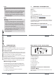
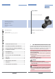
0.10.3 0.51 3
5
10
0.01
0.02
0.05
0.1
0.2
0.5
1
2
5
10
20
50
100
200
m
3
/h
0.2
0.5
1
2
5
10
20
50
100
200
500
1000
2000
3000
l/min
0.30.5 13510
30
m/s
fps
gpm
0.05
0.1
0.2
0.5
1
2
5
10
20
50
100
200
500
1000
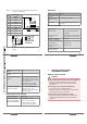
DN65
DN50 (DN65)*
DN40 (DN50)*
DN32 (DN40)*
DN25 (DN32)*
DN20 (DN25)*
DN15 (DN15 or
DN20)*
DN08
DN06
flow rate
Fluid velocity
English
25
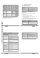
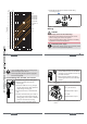
→ Assemble the electronic module and the fitting
according to Fig. 2.
1
2
3
Fig. 2: Assembling the SE30 and the S030 fitting
Wiring
danger
Risk of injury due to electrical discharge
• Shut down and isolate the electrical power source
before carrying out work on the system.
• Observe all applicable accident protection and safety
regulations for electrical equipment.
Protect the power supply
• Protect the power supply with a correctly rated
fuse if it is not protected by default.
English
25
26
• Use a shielded cable with an operating tempe-
rature limit higher than +80 °C.
• Use a high quality electrical power supply (fil-
tered and regulated).
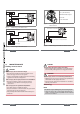
Assembling the female connector
1
2
3
4
→ Unscrew nut [1] of the cable gland.
→ Remove terminal block [3] from
housing [2].
→ Insert the cable into nut [1], through
seal [4], and into the cable gland and
finally through housing [2].
→ Connect the wires on terminal block
[3].
→ Position terminal block [3] in steps of
90° then put it back into housing [2],
pulling gently on the cable so that the
wires do not clutter the housing.
→ Tighten nut [1] of the cable gland.
English
27
6
5
→ Place seal [5] between the connector
and the fixed connector on the device
and then plug the 2508 connector into
the fixed connector.
→ Insert and then tighten screw [6] to
ensure tightness and correct electrical
contact.
Fig. 3: Assembling the female connector type 2508
(supplied)
1: V+ (12-36 V DC)
2: NPN transistor output
3: 0 V DC
4: PNP transistor output
Fig. 4: Pin assignment of the fixed connector, Hall
version
English
27