
User guide

42
Operating and functions
8.6.9. Configuring the transistor output DO1 to switch a load
when the fluid direction changes
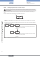
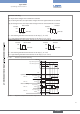
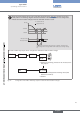
The DO1 transistor output can be configured to indicate the fluid circulation change.
When the measured flow rate is in the cut-off flow range (see chap. “8.6.16”), the flow rate is set to
0 and positive. The following diagram shows the behaviour of the DO output when it is configured to
indicate the fluid circulation changes, when the CUT-OFF function is used.
+CUTOFF
t
0
-CUTOFF
DEL DEL
DO output active
DO output inactive
measured flow rate
displayed flow rate
flow rate
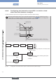
As long as the measured flow rate is lower than "-CUTOFF", the device status
LED is orange and the message "NEG. FLOW" is added to the warning message
list.
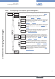
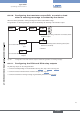
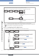
REtURN
On a version WITH relay out-
puts
On a version WITHOUT relay
outputs
OUtPUt DO1 DiRECtiO.
DO2
iNV YEs
iNV NO
0......9
→ Choose the operating, inverted or not inverted, of the
transistor output.
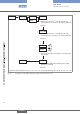
DEL. 1= 00
→ Enter the time delay before switching value (value
between 0 and 99 s).
→ Confirm.
Fig. 38: Configuration of the DO1 transistor output to indicate the fluid circulation changes
English
Type 8045