
User guide

45
Operating and functions
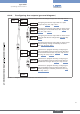
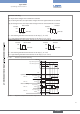
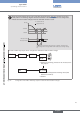
When the measured flow rate is in the cut-off flow range (see chap. “8.6.16”), the flow rate is set to
0 and positive. The following diagram shows the behaviour of the DO output when it is configured to
indicate the fluid circulation changes, when the CUT-OFF function is used.
+CUTOFF
t
0
-CUTOFF
DEL DEL
DO output active
DO output inactive
measured flow rate
displayed flow rate
flow rate
As long as the measured flow rate is lower than "-CUTOFF", the device status
LED is orange and the message "NEG. FLOW" is added to the warning message
list.
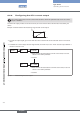
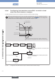
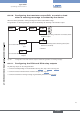
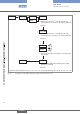
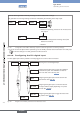
The DO2 or DO3 relay output can be configured to indicate the fluid circulation change.
OUtPUt DO2 DiRECtiO.
DO3
iNV YEs
iNV NO
0......9
→ Choose the operating, inverted or not inverted, of the
relay output.
DEL. 2= 00
→ Enter the time delay before switching value (value
between 0 and 99 s).
→ Confirm.
Fig. 41: Configuration of the DO2 or DO3 relay output to indicate the fluid circulation changes
English
Type 8045