
User guide

46
Operating and functions
When the device generates a warning message, the device status LED is orange.
The generation of a warning message can also be indicated by the switching of the relay output.
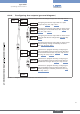
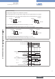
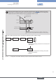
OUtPUt DO2 wARNiNG
DO3
iNV YEs
iNV NO
0......9
→ Choose the operating, inverted or not inverted, of the
relay output.
DEL. 2= 00
→ Enter the time delay before switching value (value
between 0 and 99 s).
→ Confirm.
Fig. 42: Configuration of the DO2 or DO3 relay output to indicate the generation of a warning message
→ If you do not want to adjust another parameter, go to the "END" parameter of the Parameters menu and press
ENTER
to save the settings or not and go back to the Process level.
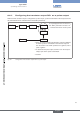
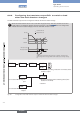
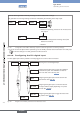
8.6.12. Configuring the DI1 digital input
The DI1 digital input makes it possible to remotely trigger one out of four device functions.
iNPUt Di1
0......9
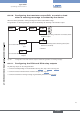
DisABLE
CALiB. 0
hOLD
sEt FLOw
REs. tOt.
REtURN
Choosing not to use the digital input.
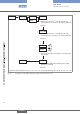
Configuring the digital input to freeze the flow rate
measurements. See “Fig. 45”.
Configuring the digital input to control the status of
the outputs and the display depending on a preset
flow rate. See “Fig. 46”.
Configuring the digital input to trigger the reset of the
daily totalizer. See “Fig. 47”.
Configuring the digital input to trigger the calibration
of the flow zero point. The calibration can also be
done in the Test menu. See “Fig. 44”.
0......9
Fig. 43: Diagram of the "INPUT" parameter of the Parameters menu
English
Type 8045