OPERATING AND MAINTENANCE MANUAL TRANSMITTER WITH DISPLAY SE 56 Release number: MASE56_DisplayFlow_EN_BU_R10_3.91.0XXX.docx – The characters of file name in bolt type indicate the software version which the manual refers to; it is visualized at the instrument start up, or by specific function on DIAGNOSTIC menu.
SE 56 2
SE 56 INDEX Introduction _________________________________________________ 4 Safety informations ___________________________________________ 4 Safety conventions ___________________________________________________ 5 Technical characteristics _______________________________________ 6 Electric characteristics ________________________________________________ 6 Environmental use conditions __________________________________________ 6 Ambient temperature _________________________________________________ 6
SE 56 INTRODUCTION These operating instructions and description of device functions are provided as part of the scope of supply. They could be modified without prior notice. The improper use, possible tampering of the instrument or parts of it and substitutions of any components not original, renders the warranty automatically void.
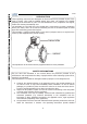
SE 56 information about the transmitter. If you are unclear on anything in these Operating Instructions, you must call the service. 5) The transmitter should only be installed after have verified technical data provided in these operating instructions and on the name plate. 6) Specialists must take care during installation and use personal protective equipment as provided by any related security plan or risk assessment.
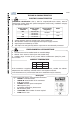
SE 56 TECHNICAL CHARACTERISTICS ELECTRIC CHARACTERISTICS Instrument classification: class I, IP67 for compact/wall-mount version, IP54 for panel-mount version (IP65 with optional transparent frontal cover), installation category II, rated pollution degree 2. Power supply versions HV LV LLV Power supply voltage 100-240V AC 18-45V AC 18-45V DC 10-35V DC Power supply frequency Pmax 44-66Hz 25VA // 20W Voltage variations must not exceed ±10% of the nominal one.
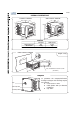
SE 56 OVERALL DIMENSIONS COMPACT VERSION 146 WALL-MOUNT VERSION 170 146 138 170 230 138 146 146 25 138 138 WEIGHT Compact 3kg 2.5kg INOX AISI 304 Alluminium Wall-mount 3.5kg 3kg PANEL-MOUNT VERSION Weight: 0.5kg 137.0 145.0 72.0 80.0 67.0 160.0 144 .0 IP65, TRASPARENT FRONTAL COVER (OPTIONAL) TORQUES To guarantee the compact/wall-mount housing’s IP degree the following torques are required: cover screws: 1.
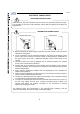
SE 56 ELECTRICAL CONNECTIONS GROUNDING INSTRUCTIONS ALWAYS ensure that the transmitter and the sensor are grounded (earthed) correctly. The grounding of the sensor and transmitter ensures that the equipment and liquid are equipotential. TRANSMITTER POWER SUPPLY Compact/wall-mount Panel-mount M3 L (+) M3 N (-) L (+) N (-) Before connecting the power supply, verify that the mains voltage is within the limits indicated on name plate.
SE 56 COMPACT/WALL-MOUNT VERSION M1 TERMINAL BLOCK Power supply Socket LOCK 1 Signalling LED: see display flags and LED warning interpretation section 2 3 4 5 6 7 8 9 10 11 12 13 14 15 16 17 18 19 20 21 22 23 24 25 26 M3 27 28 29 30 31 32 M1 M2 DIP switch, when the switch is ON, there is NO more access to the configuration functions Dangerous voltage on block 12-13: - 60V DC Max - 250V Max on commutation coils PANEL-MOUNT VERSION M1 TERMINAL BLOCK Dangerous voltage on block positions 12-13:
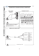
SE 56 TRANSMITTER TO SENSOR ELECTRICAL CONNECTIONS WALL-MOUNT VERSION TERMINAL BLOCK M1 1 2 E1 E2 3 C 4 SH 11 SH 12 B1 ELECTRODES E1 E2 C INPUT SH + - RS485 4-20mA B + A - 1 2 3 4 5 6 7 8 9 10 13 B2 ALL SENSORS 11 12 13 14 15 16 17 18 19 20 SH B1 COILS Sudden movements of the electrodes cable, can cause noise on measure. Max cables length: 20m. B2 SH + C 24V E OUT1 C E OUT2 SENSOR WITH PREAMPLIFIER ALL SENSORS WITH PREAMPLIFER Max cable length: 500m 10 10 (preamp.
SE 56 OPTIONAL MODULES OPTIONAL MODULES (NO RELÈ MODULES) ME200: 2 configurable on/off outputs + 1 on/off input ME201: 1 configurable on/off output + 1 high frequency output + 1 on/off input ME202: 1 4-20mA output + 2 configurable on/off output + 1 on/off input ME203: 1 RS232 port + 2 configurable on/off outputs + 1 on/off input ME204: 1 RS232 port + 2 configurable on/off outputs + 1 4-20mA output + 1 on/off input ME220, ME221, ME222: data logger, see the related manual PROFIBUS
SE 56 LEGEND OPTIONAL RELÈ MODULES ME205: 2 relay outputs with 1 NO contact + 1 NC contact each, 2A 60V AC, 60W/125VA ME207: 2 relay outputs with 1 NO contact + 1 NC contact each, 2A 250V AC, 60W/125VA SH: Cable shield, electrically connected to ground and to the housing C: Relay – common NC: Normally closed contact NO: Normally open contact Terminal block on panel-mount version Terminal block on compact/wall-mount version OUT 3 OUT 4 NO NC C OUT 4 OUT 3 C NO NC NC NO C NC
SE 56 INPUTS/OUTPUTS DIGITAL INPUT External power supply Internal power supply +24 V 10k 5 (+) 15 5 10k 3-40V DC (ON) 0-1.5V DC (OFF) 6 6 (-) 0V 20 The functions referring to the inputs could be divided in three groups: 1) 2) 3) only assignable functions to the input 1 functions that act directly on the inputs independently from the select input only assignable functions to the input 1 and only to the input 2 which interact between them For details see the following pages.
SE 56 OPERATION ON INPUT ON/OFF INPUT OPERATION STAGE (GENERIC FUNCTIONS) Auto-calibration Tmin 1 sec. = Auto zero AUTOCALIB. OFF Necessary conditions for enabling the function POS. 5.8 ENABLED (Autozero calibration external command) 3-40 V POS. 5.10 DISABLED (batch on input 1) 0-1.5 V POS. 5.11 DISABLED (batch functions assign to input 2 (optional) T Reset totalizers Necessary conditions for enabling the function BLOCK RESET 3-40 V POS. 5.1 to 5.
SE 56 OPERATION STAGE ON INPUT 1 OR 2 (BATCH FUNCTION) Start batch from remote input Necessary conditions for enabling the function INPUT 3-40V 0-1.5V Closing valve OUTPUT Opening valve POS. 5.10 or POS. 5.11 ENABLED on batch POS. 6.1 to 6.4 on end batch BATCH Start batch from consent (remote) Necessary conditions for enabling the function INPUT 3-40V 0-1.5V Closing valve Opening valve OUTPUT Opening valve BATCH Start batch from remote input with autobatch enabled 5 Sec. <5 sec. 0-1.
SE 56 OPERATION STAGE ON INPUT 1 AND 2 (BATCH FUNCTION) Start batch via input 1 stop from output selection formula 00 o 01 via input 2 Necessary conditions for enabling the function Closing valve Opening valve Closing valve Opening valve BATCH FORMULA 00 BATCH FORMULA 01 3-40V BATCH FORMULA 01 BATCH FORMULA 00 POS. 5.10 ENABLED POS. 6.1 or 6.4 on BATCH POS. 5.10 ENABLED function of formula selection 00/01 assigned to input 2 (optional) INPUT 2 0-1.
SE 56 OUTPUT WIRINGS Output on/off 1250Hz 16 (out1) 18 (out2) 43V 17 (out1) 19 (out2) Opto-insulated output with collector and emitter terminals floating and freely connectable Maximum switching voltage: 40V DC Maximum switching current: 100mA Maximum saturation voltage between collector and emitter at 100mA: 1.
SE 56 TRANSMITTER ACCESS FLAGS AND LED INTERPRETATION FLAGS FLAGS INTERPRETATION FLAG DESCRIPTION Alarm max/min activated - Interruption coils circuit ! - Signal error - Empty pipe C Calibration running S Simulation Pulse output saturation (reduce TIME of the PULSE ) LED LOCK 1 2 3 4 5 6 7 8 9 10 M3 11 12 13 14 15 16 17 18 19 20 M1 LED INTERPRETATION PERMANENT LIGHT: initialization FLASHING LIGHT (1 sec.): normal function FLASHING LIGHT (<1 sec.
SE 56 KEYBOARD SHORT PRESSING (< 1 SECOND): Increases the numeric figure or the parameter selected by the cursor Returns to the previous item on the menu Batch start/stop (when enabled) LONG PRESSING (> 1 SECOND): Decreases the numeric figure or the parameter selected by the cursor.
SE 56 START-UP VISUALIZATION PAGES The direct exposure of the transmitter to the solar rays, could damage the liquid crystal display. For the contrast set see pos. 8.
SE 56 FLOW RATE VISUALIZATION The transmitter can show a 5 digit character display for flow rate values; therefore the maximum flow rate value that can be represented on the display is 99999 (no matter the positioning of the decimal point). The minimum is 0.0025. The representable measure unit depends from sensor flow rate and diameter; the permitted units are those, set with the instrument full scale value, allow to be represented with a numerical field which the maximum value do not exceed 99999.
SE 56 ACCESS CODES Functions in the transmitter main menu are enabled by the access codes. The information in this manual is related to all the functions available with the L2 level. All the functions available through higher level are protected and reserved to the service. Description of the L2 access code (menu “11 Internal data” pos. 11.
SE 56 QUICK START MENU The user has immediate access to the Quick Start menu when the transmitter is powered up by pressing the Enter key. If access to the quick start menu does not occur, then it has been disabled through the function 8.
SE 56 ACCESS TO THE CONFIGURATION MENU The transmitter configuration menu can be accessed in two different ways: 1) by ISOCON interface 2) by keyboard of transmitter ACCESS TO THE CONFIGURATION MENU BY ISOCON INTERFACE Isocon is a Windows® software that allows to set all the transmitter functions and personalize the menu (IF2 is required), see suitable manual for details ACCESS TO THE CONFIGURATION MENU BY THE KEYBOARD Functions can be accessed by the keyboard in two different ways: The Quick start me
SE 56 EXAMPLE: modifying the full scale value from 4dm³/s to 5dm³/s, from the “Quick start menu” Access to the function “Fs1” Enter in the “Quick start menu” Push Repeatedly Change the value Confirm the new value Long push Main page 25
SE 56 EXAMPLE: modifying the full scale value from 4dm³/s to 5dm³/s, from the “Main Menu” (quick start menu enabled) Enter in the “Quick start menu” X 6 TIMES Access to the “Scale” menu Change the value Move cursor down to Main menu Access to the “Main Menu” Confirm the keycode Push repeatedly Access to the function “Fs1” Long push Confirm the new value Main page Long push 26
SE 56 CONFIGURATION FUNCTIONS (functions with access code < 3, those with symbol “*” see the next section) Attention: The menu functions in grey colour are visualized on display only with other active functions or with optional modules 1.1 1.2 1.3 1.4 Insert ND (diameter size) of sensor (0-3000mm) Sensor calibration data, visualized on sensor's label Type of sensor: Enter the first two characters of the sensor serial number (see sensor label) Position for insertion sensors: 0=1/8DN, 1=1/2DN, 2=7/8DN 1.
SE 56 5.1* 5.2* 5.3* 5.4* 5.5 5.6 5.7* Total direct (positive) flow totalizers reset enable Partial direct (positive) flow totalizers reset enable Total reverse (negative) flow totalizers reset enable Partial reverse (negative) flow totalizers reset enable Reset totalizers of pulse from digital input (see page 14) Totalizers counting lock command (see page 14) Block measures command 5.8* Autozero calibration external command 5.9 Range change external command (see function 3.5) 5.
SE 56 9.1* 9.2 9.3 9.4 9.5 9.6 9.7 9.8 9.9 Date and time set Automatic data logger enable Interval time for the data logging function: 1, 2, 3, 6, 8, 12, 24, 48 hours Displaying of the data stored in the data logger Displaying of the last 64 alarms stored in the data logger Visualization function of minimum and maximum peak of flow rate Logged data cancel function Reset all alarm events Reset all minimum and maximum peak of flow rate stored 10.1* 10.2* 10.3* 10.
SE 56 FUNCTIONS DESCRIPTION (description of the functions with access code< 3) Identification of the function (not visualized on display) MENU 1-SENSOR (POS. 1.1) Nominal diameter of sensor [ND= XXXX] Transmitter request Menu visualized on the transmitter (from 1 to 11) Synthetic description of the function The following pages give a description of the most important functions and how they can be changed or enabled/disabled by the user MENU 1 - SENSOR (POS. 1.8) Electrodes cleaning [El.
SE 56 where fsmax is the maximum full scale value corresponding to the sensor, equal to a 10m/s liquid speed. The measure units are shown as appear on the display. The British and American units are diversified by using capital and small characters.
SE 56 MENU 3 - MEASURE (POS. 3.1) Damping [Damping=OFF/SMARTX /(time)] This section of the manual is extremely important. The correct filter settings ensures a proper response of the instrument to the measured flow rate. The available dampening filter values range between no damping (damping=OFF) and maximum damping based of 1000 seconds (Damping=1000). The three diagrams below demonstrate the instrument behavior with different dampening settings with flow rate changes in the range of 1-100%.
SE 56 (POS. 3.5) Automatic scale change enable [Autorange=ON/OFF] Enables the automatic change of scale. The meter may have two different working ranges in order to suit to the variable process conditions. In order to get the best results out of this function it is important range N.2 (Fs2) if enabled is bigger than N.1 (Fs1). When the flow rate increases and reaches the 100% of the full scale 1, then the meter automatically switches to scale 2.
SE 56 MENU 5 - INPUTS (POS. 5.1-4) Reset totalizer enable [T/P+/-RESET=ON/OFF] When one of this function is enabled, the related totalizer may be reset through the on/off input. (POS. 5.7) “Block measures” command block measures enable [Meas. lock=ON/OFF] When this function is active (ON), applying a voltage on the on input terminals, the measurement is stopped, the meter will display zero flow. (POS. 5.
SE 56 (POS. 6.5-6) Function and the range of current output n.1-2 [Out mA1-2=X÷XX+] The function associated to the signal current on output N.1-2. The current output N.1 is optional and it is mounted on the main board.
SE 56 (POS. 8.13-16) Total/partial totalizers reset [T/P/-/+ reset] Activates the reset of total and partial flow totalizer. These functions are activated by pressing the key Enter during the visualization of the function itself. When "EXECUTE?" is required, press long Enter to proceed. Press any other key to cancel the operation. MENU 9 - DATA LOGGER (POS. 9.1) Date and time set [ = dd/mm/yy hh:mm] Date and time set.
SE 56 The batch functions allow the user to set the transmitter to measure a defined volume of fluid and control outputs. An example is opening and closing a value after a predefined volume has passed the sensor. The user sets the volume and the control parameters by the transmitter through the follwing fuctions (Main menu function group 12 ‘Batch’) MENU 12 - BATCH Menu visualized only with batch active (output on batch and/or pos. 5.9 enable or 5.10 on batch) (POS. 12.1) Number of batch samples [N.
SE 56 BATCH FUNCTION CONFUGURATION ENABLE BATCH Select one of the following functions to enable and configure the batch on the transmitter: POS. 5.9-5.10: START/STOP batch from input POS. 6.1-6.2: assign one of the functions ouputs one and/or two Some examples of operation of such functions are visualized from page 14.
SE 56 START STOP BATCH START: it is possible to activate the start of batch in two different ways: 1. From remote input: assigning the functions of start/stop batch to the input 1 (pos. 5.9) or input 2 (pos. 5.10) and using the inputs like visualized from page 14. From keyboard: short pressing of the key N.B.: The start of batch from keyboard is always initiated on the release of the key. The function is not available with the batch consent (pos. 12.7) function enabled. 2.
SE 56 ALARM MESSAGES CAUSES AND ACTIONS TO BE TAKEN Messages ERRORS ACTION TO TAKE NO ALARMS All works regularly MAX ALARM The flow rate is higher than the maximum threshold set Check the maximum flow rate threshold set and the process conditions MIN ALARM The flow rate is lower than the minimum threshold set Check the minimum flow rate threshold set and the process conditions FLOW RATE >FS PULSE/FREQ>FS EMPTY PIPE ----- The flow rate is higher than the full scale value set on the instrumen
SE 56 APPENDIX: DISPLAY ROTATION PROCEDURE Fixing screw of board Pic.4 1 Pic.5 3 4 Pic.1 2 Unscrew the screw as indicated in pic. 1 Take off the flat cable Pic.2 Rotate the display to the desired location, verify the correct set of the seal, the cleaning of the contact surfaces it set the display housing. Place the fixing angles in the suitable positions (pic. 5) and screw down firmly until they make contact with the display housing.
CONFORMITY DECLARATION declares under the own responsibility that the product Transmitter model SE 56 Sensors model: S051 – S054 – S055 – S056 to which this declaration refers, is in compliance with the following Harmonized European Norms: EN 61010-1:2010 EN 61326-1:2006 and therefore answering to essential requirement of CE directives: 2006/95/CE (Low voltage directive – LVD) 2004/108/CE (Electromagnetic Compatibility Directive – EMC) 04/03/2011
%(',(181*6 81' ,167$//$7,216$1/(,781* '85&+)/866 75$160,77(5 0,7 $1=(,*( 6( Ausgabe Nummer: MASE56-DisplayFlow_DE_BU_R10_3_91.0XXX.docx – Die letzten drei Zeichen des Dateinamens stehen für die Software-Version, die beim Einschalten des Gerätes angezeigt wird und auf die sich das Handbuch bezieht.
SE 56 INHALTSVERZEICHNIS Einleitung ___________________________________________________ 3 Sicherheitshinweise ___________________________________________ 3 Sicherheitszeichen ___________________________________________________ 4 Technische Daten _____________________________________________ 5 Elektrische Daten ____________________________________________________ 5 Umgebungsbedingungen ______________________________________________ 5 Betriebstemperatur _________________________________________________
SE 56 EINLEITUNG Diese Bedienungsanleitung und Beschreibung der Gerätefunktionen ist integraler Bestandteil des Gerätes. Änderungen ohne Vorankündigung sind vorbehalten. Bei unsachgemäßer Verwendung, Veränderungen des Gerätes oder seiner Komponenten oder Einsatz von nicht originalen Ersatzteilen verfällt sofort jeglicher Gewährleistungsanspruch.
SE 56 4) Die Fachleute müssen diese Bedienungsanleitung gelesen und verstanden haben und die darin enthaltenen Anweisungen befolgen. Wenn Ihnen irgend etwas in dieser Bedienungsanleitung unklar ist, müssen Sie den Kundendienst anrufen. Die Bedienungsanleitung liefert ausführliche Informationen über den Transmitter. 5) Reparaturen dürfen nur durchgeführt werden, wenn ein Originalersatzteil-Kit verfügbar ist und diese Reparaturarbeiten ausdrücklich genehmigt sind.
SE 56 TECHNISCHE DATEN ELEKTRISCHE DATEN Geräte-Klassifizierung: Schutzklasse I, IP67 bei Kompakt/Wandmontage-Version, IP54 bei Schalttafel-Einbau-Version (IP65 mit optionaler transparenter Frontabdeckung), Anlagenkategorie II, bewerteter Verschmutzungsgrad 2. Stromversorgungsversionen HV VersorgungsStromfrequenz Pmax spannung 100-240V AC 44-66Hz 25VA 18-45V AC LV 18-45V DC // 20W LLV 10-35V DC Spannungsänderungen dürfen ±10 % der Nennspannung nicht überschreiten.
SE 56 AUßENMAßE KOMPAKTAUSFÜHRUNG WANDMONTAGE-AUSFÜHRUNG GEWICHT Kompakt 3 kg 2,5 kg Edelstahl AISI 304 Aluminium Wandmontage 3,5 kg 3 kg SCHALTTAFEL-AUSFÜHRUNG Gewicht: 0,5 kg IP65, TRANSPARENTE FRONT,3 75$63$5(17 )5217$/ &29(5 237,21$/ ABDECKUNG (OPTIONAL) ANZUGSDREHMOMENTE Um die IP-Schutzklasse des Kompakt/Wandmontage-Gehäuses zu garantieren, sind die folgenden Drehmomente erforderl
SE 56 ELEKTRISCHE ANSCHLÜSSE ERDUNGSANWEISUNGEN Damit der Transmitter ordnungsgemäß funktioniert, MÜSSEN Transmitter, Sensor und Flüssigkeit immer das gleiche Potenzial aufweisen. Erden Sie Sensor und Transmitter also IMMER. STROMVERSORGUNG DES TRANSMITTERS Kompakte oder Wandmontage Ausführung SchalttafelAusführung 0 / 0 1 / 1 Stellen Sie vor dem Anschließen der Stromversorgung unbedingt sicher, dass die Versorgungsspannung in dem auf dem Typenschild angegebenen Bereich liegt.
SE 56 KLEMMENLEISTE M1 FÜR MODELL IN KOMPAKTAUSFÜHRUNG UND ZUR WANDMONTAGE 6WURPYHUVRUJXQJ IF2-Anschluss-Fassung /2&. Anzeige-LED: siehe Abschnitt zu Statusanzeigen und Bedeutung von LED-Warnungen 0 0 0 DIP-Schalter, wenn der Schalter auf ON steht, besteht kein Zugriff mehr auf die Parametrierfunktionen Gefährliche Spannung an Klemmen 12-13: - 60 V= max. - 250 V max.
SE 56 ELEKTRISCHE ANSCHLÜSSE ZWISCHEN SENSOR UND TRANSMITTER WANDMONTAGE KLEMMENLEISTE M1 ( ( & 6+ 6+ % (/(.752'(1 ( ( & 6+ % (,1 *$1* 56 % $ P$ $//( 6(1625(1 6+ % % 638/(1 Plötzliche Bewegungen der Elektrodenkabel können ein Verrauschen des Messwertes verursachen. Max. Kabellänge: 20 m. 6+ & ( 9 $86 & ( $86 9 AUSFÜHRUNG MIT VORVERSTÄRKER $//( 6(1625(1 0,7 9259(567b5.
SE 56 OPTIONALE MODULE OPTIONALE MODULE (OHNE RELAIS) LEGENDE 2 programmierbare Digital-Ausgänge + 1 Digital-Eingang 1 programmierbarer Digital-Ausgang + 1 Hochfrequenzausgang + 1 Digital-Eingang 1 0/4…20 mA-Ausgang + 2 programmierbare Digital-Ausgänge + 1 Digital-Eingang 1 RS232/Ausgang + 2 programmierbare Digital-Ausgänge + 1 Digital-Eingang 1 RS232-Ausgang + 2 programmierbare Digital-Ausgänge + 1 0/4…20mA-Ausgang + 1 Digital-Eingang Data logger: siehe separates Handbuch
SE 56 LEGENDE OPTIONALE RELAIS MODULE 2 Relaisausgänge mit 1 NO-Kontakt + je 1 NC-Kontakt, 2 A 60 V AC, 60 W/125 VA 2 Relaisausgänge mit 1 NO-Kontakt + je 1 NC-Kontakt, 2 A 250 V AC, 60 W/125 VA SH: Kabelabschirmung elektrisch mit Erde und Gehäuse verbunden C: Relais – Common NC: stromlos geschlossen (Öffner) NO: stromlos geöffnet (Schließer) Klemmenleiste bei Tafeleinbau-Version Klemmenleiste bei Kompakt/Wandmontage-Version 287 287 12 1& & 12 1& 1& & 287 287 12
SE 56 EINGÄNGE/AUSGÄNGE DIGITALEINGANG Externe Stromversorgung N Interne Stromversorgung V N 9'& 21 9'& 2)) V Die Funktionen für die Eingänge lassen sich in drei Gruppen unterteilen : 1) 2) 3) Funktionen nur für Eingang 1 Funktionen, die unabhängig vom gewählten Eingang direkt auf die Eingänge wirken Funktionen, die nur zu Eingang 1 und Eingang 2 zugeordnet werden können, und die miteinander in Wechselwirkung stehen Für Einzelheiten siehe die folgen
SE 56 ANSTEUERUNG DES DIGITAL-EINGANGS STATUS-AUSWERTUNG (GENERISCHE FUNKTIONEN) Auto-Kalibrierung Tmin 1 sek. = automatischer Nullpunkt $872&$/,% 2)) Voraussetzungen für die Aktivierung der Funktion 9 POS. 5.8 AKTIVIERT (Automatischer Nullabgleich auf externen Befehl) POS. 5.10 DEAKTIVIERT (Dosiersteuerung über Eingang 1) 9 7 POS. 5.
SE 56 STATUS-AUSWERTUNG EINGANG 1 ODER 2 (DOSIERFUNKTION) EINGANG Start Dosierung über Eingangs-Impuls 3-40V 0-1.5V 3-40V 0-1.5V AUSGANG Ventil öffnen DOSIERUNG Start Dosierung über externen Eingang mit Auto-Dosierung aktiviert 3-40V 5 Sec. <5 sec. 0-1.
SE 56 STATUS-AUSWERTUNG EINGANG 1 UND 2 (DOSIERFUNKTION) EINGANG 1 6WDUW 'RVLHUXQJ EHU (LQJDQJ 6WRSS YRP $XVJDQJ GHU $XVZDKOIRUPHO RGHU EHU (LQJDQJ Start 3-40V Ventil Ventil schließen öffnen DOSIERFORMEL 00 POS. 5.10 AKTIVIERT POS. 6.1 oder 6.4 auf „DOSIERUNG“ POS. 5.10 AKTIVIERT Funktionsauswahl für Formel 00/01 zugewiesen auf Eingang 2 (optional) Ventil schließen en DOSIERFORMEL 01 3-40V EINGANG 2 Ventil öffnen AUSGANG 0-1.
SE 56 AUSGANGSVERDRAHTUNG Digital-Ausgang 1250 Hz 16 (out1) 18 (out2) 43V 2SWLVFK LVROLHUWHU $XVJDQJ PLW .ROOHNWRU XQG (PLWWHU DQVFKOXVV SRWHQ]LDOIUHL XQG IUHL EHOHJEDU 0D[LPDOH 6FKDOWVSDQQXQJ 9 '& 0D[LPDOHU 6FKDOWVWURP P$ 0D[LPDOH 6lWWLJXQJVVSDQQXQJ ]ZLVFKHQ .ROOHNWRU XQG (PLWWHU P$ EHL 9 '& 0D[LPDOHV 6FKDOWIUHTXHQ] /DVW DQ .
SE 56 TRANSMITTERZUGANG BEDEUTUNG DER FLAGS UND LED FLAGS FLAG ! C S BEDEUTUNG DER FLAGS BESCHREIBUNG Alarm max/min aktiviert - Unterbrechung der Spulenschaltung - Signalfehler - Rohr leer Kalibrierung wird durchgeführt Simulation ,PSXOVDXVJDQJVVlWWLJXQJ =(,7,038/6 YHUULQJHUQ LED /2&. 0 0 BEDEUTUNG DER LED DAUERLEUCHTEN: Initialisierung BLINKEN (1 Sek.): Normale Funktion BLINKEN (<1 Sek.
SE 56 TASTATUR KURZ DRÜCKEN (< 1 SEKUNDE): Erhöht den Zahlenwert oder den Parameter, der mit dem Cursor markiert wurde Rückkehr zum vorherigen Menüpunkt Dosierung Start/Stopp (sofern aktiviert) LANG DRÜCKEN (> 1 SEKUNDE): Vermindert den Zahlenwert oder den Parameter, der mit dem Cursor markiert wurde.
SE 56 ANZEIGESEITEN AUFRUFEN Die LCD-Anzeige des Transmitters kann durch direkte Sonneneinstrahlung beschädigt werden. Hinweis: Kontrasteinstellung siehe Pos. 8.
SE 56 DURCHFLUSSANZEIGE Der Transmitter kann Durchflusswerte auf einer 5-Zeichen-Anzeige darstellen; dies bedeutet, dass der auf dem Display maximal darstellbare Durchfluss 99999 ist (unabhängig von der Position des Kommas). Der Minimalwert ist 0,0025. Die darstellbaren Messeinheiten hängen vom Durchfluss und Durchmesser des Sensors ab; die zulässigen Einheiten sind diejenigen, die beim Messbereichsendwert gewählt wurden.
SE 56 ZUGANGSCODES Funktionen im Hauptmenü des Transmitters werden durch die Zugangscodes aktiviert. Die Informationen in diesem Handbuch beziehen sich auf alle Funktionen, die in Zugangsstufe L2 verfügbar sind. Alle Funktionen höherer Zugangsstufen sind dem Service vorbehalten und nicht verfügbar. Beschreibung der Zugangscodes für L2 (Menü “11 Interne Daten” Pos. 11.
SE 56 QUICKSTARTMENÜ Nachdem der Transmitter eingeschaltet wurde hat der Benutzer sofort Zugang zum Quickstartmenü, durch Drücken der Taste Enter. Wenn kein Zugang zum Quickstartmenü erfolgt, wurde es über Funktion 8.
SE 56 ZUGANG ZUM PARAMETRIERMENÜ Das Konfigurationsmenü des Transmitters kann auf zwei verschiedene Weisen aufgerufen werden: 1) über die ISOCON-Schnittstelle 2) über das Tastenfeld des Transmitters ZUGANG ZUM KONFIGURATIONSMENÜ ÜBER DIE ISOCON-SCHNITTSTELLE Isocon ist eine Windows® Software, mit der alle Transmitter-Funktionen eingestellt und das Menü angepasst werden können (IF2X ist erforderlich), für Einzelheiten siehe die entsprechende Bedienungsanleitung.
SE 56 BEISPIEL: Ändern des Messbereichsendwertes von 4dm³/s auf 5dm³/s, über das “Quickstartmenü” Zugang zu Funktion "Fs1" Öffnen des "Quickstartmenüs" Mehrmals drücken Ändern des gewählten Zahlenwerts Neuen Wert bestätigen Lang drücken Hauptseite 24
SE 56 BEISPIEL: Ändern des Messbereichsendwertes von 4dm³/s auf 5dm³/s, über “Hauptmenü” (bei aktiviertem Quickstartmenü) Öffnen des "Quickstartmenüs 6 MAL auf 1 stellen Öffnen des Menüs "Scales" Ändern des Wertes Bis auf „Main Menu“ durchlaufen Öffnen des "Hauptmenüs" Bestätigen Sie den Tastencode Mehrmals drücken Zugang zu Funktion "Fs1" Lang drücken Neuen Wert bestätigen Hauptseite Lang drücken 25
SE 56 PARAMETRIERFUNKTIONEN (Funktionen mit Zugangscode < 3, diejenigen mit dem Symbol „*“, siehe nächsten Abschnitt) Achtung: Grau dargestellte Funktionen werden nur mit anderen Funktionen angezeigt, oder mit optionalen Modulen 1.1 Tragen Sie den Nenndurchmesser entsprechend dem Typenschild des Sensors (0-3000 mm) ein 1.2 1.3 Kalibrierdaten des Sensors sind auf dem Typenschild des Sensors angegeben Typ des Sensors: Geben Sie die ersten zwei Zeichen der Serien-Nr.
SE 56 5.1* Gesamtaktivierung für Zurücksetzung des Vorwärtsdurchfluss-Mengenzählers (positiv) 5.2* Teilaktivierung für Zurücksetzung des Vorwärtsdurchfluss-Mengenzählers (positiv) *HVDPWDNWLYLHUXQJ IU =XUFNVHW]XQJ GHV 5FNZlUWVGXUFKIOXVV 0HQJHQ]lKOHUV QHJDWLY 7HLODNWLYLHUXQJ IU =XUFNVHW]XQJ GHV 5FNZlUWVGXUFKIOXVV 0HQJHQ]lKOHUV QHJDWLY 5.5 Zähler zurücksetzen durch Impuls am Digitaleingang (siehe Seite 13) 5.6 Sperrbefehl für Mengenzähler (siehe Seite 13) 5.
SE 56 9.1* 9.2 9.3 9.4 9.5 9.6 9.7 9.8 9.
SE 56 %(6&+5(,%81* '(5 )81.7,21(1 %HVFKUHLEXQJ GHU )XQNWLRQHQ PLW =XJDQJVFRGH )XQNWLRQVNHQQXQJ QLFKW DQJH]HLJW MENÜ 1.SENSOR (POS. 1.1) Nenndurchmesser des Sensors [ND= XXXX] Transmitteranforderung 0HQ DQJH]HLJW LP 'LVSOD\ YRQ ELV 6\QWKHWLVFKH %HVFKUHLEXQJ GHU )XQN WLRQ Auf den folgenden Seiten werden die wichtigsten Funktionen und ihre Einstellung oder Aktivierung/Deaktivierung durch den Benutzer beschrieben MENÜ 1 - SENSOR (POS. 1.8) Elektrodenreinigung [El.
SE 56 In der folgenden Tabelle sind die verfügbaren Messeinheiten zusammen mit ihrem Umrechnungsfaktor bezogen auf 1 dm3 und 1 kg gezeigt. Der Transmitter akzeptiert jede Kombination von Messeinheiten, solange die folgenden Bedingungen eingehalten werden: Zahlenwert d 99999 1/25 fsmax d Zahlenwert d fsmax. Hierbei ist fsmax der maximale Messbereichsendwert für den jeweiligen Sensor bei einer Flüssigkeitsgeschwindigkeit von 10 m/s. Die folgenden Messeinheiten werden in der Anzeige dargestellt.
SE 56 MENÜ 3 - MESSEN (POS. 3.1) Dämpfung [Damping=OFF/SMART X/(time)] Dieser Handbuchabschnitt ist sehr wichtig. Eine korrekte Einstellung der Filter sorgt für eine geeignete Reaktion des Geräts auf den gemessenen Durchfluss. Die verfügbaren Filterwerte reichen von keiner Dämpfung (Damping=OFF) bis zu einer maximalen Dämpfung von 1000 Sekunden (Damping=1000). Die drei folgenden Diagramme zeigen das Verhalten des Geräts je nach Parametrierung der Filter für Durchflussveränderungen von 1-100 %.
SE 56 (POS. 3.
SE 56 MENÜ 5 - EINGÄNGE (POS. 5.1-2-3-4) Zählerrücksetzung freigeben [T/P+/-RESET=ON/OFF] Wenn eine dieser Funktionen aktiviert ist, kann der entsprechende Zähler über den digitalen Eingang zurückgesetzt werden. (POS. 5.7) Aktivierungsbefehl „Messungen sperren“ [Meas. lock=ON/OFF] Wenn diese Funktion aktiviert ist (ON), wird die Messung durch Anlegen einer Spannung an den Eingangsklemmen gestoppt, und der Transmitter zeigt einen Durchfluss von 0 an. (POS. 5.8) Externer Befehl für autom.
SE 56 MENÜ 6 - AUSGÄNGE (POS. 6.1-4) Funktion für aktive/inaktive Ausgänge 1-2-3-4 [OUT1=XXXXXX] Hiermit wählen Sie die mit dem digitalen Ausgang 1 verbundene Funktion. Die Funktionen finden Sie in der nachfolgenden Tabelle. Die Ausgänge 3-4 sind optional; außerdem ist Ausgang 4 der einzige, der die Frequenz von 12,5 KHz erreichen kann. FUNKTION FÜR AUSGANG 1, 2, 3, 4 2)) '($.7,9,(57 ,03 ,038/6 $1 .$1$/ )h5 326,7,9(1 '85&+)/866 ,03 ,038/6 $1 .
SE 56 Bei Vorliegen eines Hardwarealarms HW ALARM (unterbrochene Spulen, Leerrohr, Messfehler) wird der aktuelle Wert mit der Funktion "mA VAL. FAULT" (Pos. 4.7) parametriert und als Prozentsatz eines feststehenden Strombereichs ausgedrückt, wobei: 0 % = 0 mA und 110 % = 22 mA.
SE 56 MENÜ 10 - DIAGNOSE [Calibration] (POS. 10.1) Kalibrierung des Transmitters Ermöglicht das Kalibrieren des Messgerätes. Diese Funktion wird durch Drücken der Eingabetaste bei Anzeige der Funktion aktiviert. Nach der Abfrage "EXECUTE?" halten Sie die Eingabetaste mindestens zwei Sekunden lang gedrückt. Sie beenden den Vorgang, indem Sie auf eine andere Taste drücken. Die Flüssigkeit muss in diesem Zeitraum absolut still stehen. (POS. 10.
SE 56 MENÜ 12.DOSIERUNG Menü wird nur angezeigt, wenn die Dosierfunktion aktiv ist (Ausgang an Dosierung und/oder Pos. 5.9 aktiviert oder 5.10 auf Dosierung) (POS. 12.1) Anzahl der Dosierproben [N.samples=XXX] Anzahl der erforderlichen Dosierzyklen, um den Kompensationswert zu definieren. Mit dieser Funktion kann der Durchschnittswert für die automatische Kompensation der Systemverzögerung (Pos. 12.3). automatisch bestimmt werden.
SE 56 PARAMETRIEREN DOSIERFUNKTION DOSIERUNG AKTIVIEREN Aktivieren Sie eine der folgenden Funktionen, um die Dosierung im Transmitter zu aktivieren und zu parametrieren: POS. 5.9-5.10: START/STOP Dosierung nach Eingang POS. 6.1-6.2: Weisen Sie eine der Funktionen einem der zwei Ausgänge zu Einige Beispiele für die Wirkung solcher Funktionen sind ab Seite 14 dargestellt. $1=(,*(6(,7( %(, $.7,9,(57(5 '26,(5)81.
SE 56 DOSIERUNG STARTEN/ANHALTEN START: Sie können eine Dosierung auf zweierlei Weise starten: 1.Über einen digitalen Eingang: Zuweisen der Start/Stopp-Funktionen zu Eingang 1 (POS. 5.9) oder Eingang 2 (POS. 5.10) und Verwenden der Eingänge wie auf Seite 14 dargestellt. 2.Von der Tastatur: Taste kurz drücken.
SE 56 ALARMMELDUNGEN URSACHEN UND GEGENMAßNAHMEN Meldungen *(*(10$1$+0( BESONDERHEITEN NO ALARMS $OOHV DUEHLWHW VW|UXQJVIUHL MAX ALARM 'XUFKIOXVV K|KHU DOV GHU HLQJHVWHOOWH 0D[LPDOZHUW MIN ALARM 'XUFKIOXVV QLHGULJHU DOV GHU HLQJHVWHOOWH 0D[LPDOZHUW FLOW RATE >FS 'XUFKIOXVV K|KHU DOV GHU DP *HUlW HLQJHVWHOOWH 0HVVEHUHLFKV HQGZHUW PULSE/FREQ>FS 'HU 3XOVDXVJDQJ GHV *HUlWHV LVW JHVlWWLJW XQG NDQQ GLH HUIRUGHU OLFKH ,PSXOVDQ]DKO QLFKW HU]HXJHQ EMPTY PIPE BATCH ALARM INPUT NOISY EXC
SE 56 ANHANG: DREHUNG DER ANZEIGE %HIHVWLJXQJVVFKUDXEH GHU 3ODWLQH Bild 4 1 Bild 5 3 4 Pic.1 2 /|VHQ 6LH GLH 6FKUDXEHQ LQ JHHLJQHWHU :HLVH 'UHKHQ 6LH GLH $Q]HLJH LQ GLH JHZQVFKWH 3RVLWLRQ VWHOOHQ 6LH VLFKHU GDVV GLH 'LFKWXQJ NRUUHNW DQJH SDVVW LVW XQG GDVV GLH .RQWDNWVWHOOHQ VDXEHU VLQG 6HW]HQ 6LH GDQQ GDV 'LVSOD\ LQ GLH $XIQDKPH HLQ 6FKLHEHQ 6LH GLH .
KONFORMITÄTSERKLÄRUNG erklärt in eigener Verantwortung, dass das Produkt Transmitter-Modell SE 56 Sensoren-Modelle S051 – S054 – S055 – S056 auf das sich diese Erklärung bezieht, konform zu den folgenden harmonisierten Europäischen Normen ist: CEI EN 61010-1:2010 CEI EN 61326-1:2006 und deshalb die Anforderungen der folgenden EU-Verordnungen erfüllt: 2006/95/EG (Niederspannungsdirektive – LVD) 2004/108/EG (EMV-Direktive – EMC) 04/03/2011
MANUEL D'INSTALLATION ET D'UTILISATION TRANSMETTEUR DE DEBIT AVEC AFFICHEUR SE 56 Numéro de publication : MASE56_DisplayFlow_FR_BU_R10_3.91.0XXX.docx – Les caractères en gras du nom de fichier correspondent à la version du logiciel, visible au démarrage de l’instrument ou avec une fonction spécifique du menu Diagnostique auquel fait référence le manuel.
SE 56 INDEX Introduction _________________________________________________ 3 Consignes de sécurité _________________________________________ 3 Signaux de sécurité __________________________________________________ 4 Caractéristiques techniques _____________________________________ 5 Caractéristiques électriques ____________________________________________ 5 Conditions ambiantes d’utilisation _______________________________________ 5 Température de fonctionnement ______________________________________
SE 56 INTRODUCTION Les présentes instructions d'utilisation et descriptions des fonctions de l'appareil s'appliquent à son domaine d'utilisation prévu. Elles sont sujettes à modification sans préavis. Toute utilisation inadéquate, modification non-autorisée de l'appareil ou de ses pièces, ainsi que tout remplacement d'un ou plusieurs des composants d'origine invalident automatiquement la garantie.
SE 56 4) Ces spécialistes doivent avoir lu et compris le présent manuel et observer ses instructions. En cas du moindre doute sur les présentes instructions d'utilisation, l'assistance doit être contactée. Ces instructions fournissent des informations détaillées sur le transmetteur. 5) Des réparations ne peuvent être entreprises qu’en possession de pièces de rechange du fabricant et si ces travaux sont expressément autorisés.
SE 56 CARACTÉRISTIQUES TECHNIQUES CARACTÉRISTIQUES ÉLECTRIQUES Classification de l’instrument : classe I, IP67 pour la version compacte/murale, IP54 pour la version encastrable (IP65 avec un capot transparent optionnel), catégorie d’installation II, degré de pollution nominal 2.
SE 56 DIMENSIONS GÉNÉRALES VERSION ¬ MONTAGE MURAL VERSION COMPACTE POIDS Compacte 3 kg 2,5 kg INOX AISI 304 Aluminium Montage mural 3,5 kg 3 kg VERSION ENCASTRABLE Poids : 0,5 kg IP65, CAPOT TRANSPARENT ,3 75$63$5(17 )5217$/ &29(5 (OPTIONNEL) 237,21$/ COUPLES DE SERRAGE Pour assurer le niveau de protection IP du boîtier en version compacte/murale, les couples de serrage suivants sont
SE 56 BRANCHEMENTS ELECTRIQUES INSTRUCTIONS DE MISE A LA TERRE TOUJOURS s'assurer que le transmetteur et le capteur sont mis à la terre correctement. La mise à la terre du capteur et du transmetteur permet de garantir que l'équipement et le fluide ont le même potentiel.
SE 56 BORNIER M1 POUR LES VERSIONS COMPACTES ET À MONTAGE MURAL Alimentation électrique Port IF2 /2&. Voyant de signalisation : voir la partie l’interprétation des indicateurs et du voyant. sur 0 0 0 Interrupteur DIP, lorsqu’il est sur ON, on ne peut PLUS accéder aux fonctions de configuration.
SE 56 BRANCHEMENTS ÉLECTRIQUES ENTRE LE TRANSMETTEUR ET LE CAPTEUR VERSION A MONTAGE MURAL BORNIER M1 ( ( & 6+ 6+ % ( (/(&752'(6 6+ & ( 5 56 $ % ,1387 ENTRÉE P$ % TOUS LES CAPTEURS $// 6(16256 6+ Des mouvements brusques du câble des électrodes peuvent provoquer des bruits lors de la mesure Longueur max.
SE 56 MODULES EN OPTION MODULES EN OPTION (PAS DE RELAIS) LÉGENDE 2 sorties on/off configurables + 1 entrée on/off 1 sortie on/off configurable + 1 sortie haute fréquence + 1 entrée on/off 1 sortie 4-20mA + 2 sorties configurables + 1 entrée on/off on/off 1 port RS232 + 2 sorties configurables + 1entrée on/off on/off 1 port RS232 + 2 sorties on/off configurables + 1 sortie 4-20mA + 1 entrée on/off Data logger (enregistreur de données) : voir le manuel correspondant.
SE 56 MODULES RELAIS EN OPTION LÉGENDE 2 sorties relais avec 1 contact NO (normalement ouvert) + 1 contact NC (normalement fermé) chacune, 2A 60 V ac, 60 W/125 Va SH : blindage de câble, branché électriquement à la terre et au boîtier 2 sorties relais avec 1 contact NO (normalement ouvert) + 1 contact NC (normalement fermé) chacune, 2A 250 V ac, 60 W/125 Va NC : contact normalement fermé C : relais – commun NO : contact normalement ouvert Bornier de la version encastrable Bornie
SE 56 ENTRÉES / SORTIES ENTRÉE NUMÉRIQUE Alimentation électrique interne Alimentation électrique externe N N 9'& 21 9'& 2)) Les fonctions faisant référence aux entrées peuvent être divisées en trois groupes : 1) 2) 3) fonctions uniquement attribuables à l’entrée 1 fonctions agissant directement sur les entrées indépendamment de l’entrée sélectionnée fonctions uniquement attribuables à l’entrée 1 et uniquement à l’entrée 2 et interagissant les unes ave
SE 56 FONCTIONNEMENT DE L’ENTRÉE ON/OFF FONCTIONNEMENT DES ENTRÉES (FONCTIONS GÉNÉRIQUES) Calibration automatique Tmin 1 sec. = auto zéro $872&$/,% 2)) Conditions nécessaires pour activer la fonction 9 POS. 5.8 ACTIVÉE (commande externe calibration auto-zéro) POS. 5.10 DÉSACTIVÉE (dosage sur l’entrée 1) 9 POS. 5.
SE 56 FONCTIONNEMENT DE L’ENTRÉE 1 OU 2 (FONCTION DOSAGE) Démarrer dosage à partir de l’entrée distante ENTRÉE 3-40V 0-1.5V Conditions nécessaires pour activer la fonction Fermeture vanne sur SORTIE Ouverture vanne POS. 5.10 ou POS. 5.11 ACTIVÉE DOSAGE POS. 6.1 à 6.4 sur FIN DE DOSAGE DOSAGE ENTRÉE Démarrer dosage par signal statique 3-40V 0-1.5V <5 sec.
SE 56 FONCTIONNEMENT DES ENTRÉES 1 ET 2 (FONCTION DOSAGE) Démarrer dosage sur l’entrée distante 1 Arrêt à partir de la sortie sélection des formules 00 ou 01 à partir de l’entrée distante 2 ENTRÉE 1 Conditions nécessaires pour activer la fonction Début 3-40V 0-1.5V Ouverture vanne Fermeture vanne FORMULE DOSAGE 01 FORMULE DOSAGE 00 3-40V FORMULE DOSAGE 01 FORMULE DOSAGE 00 POS. 5.10 ACTIVÉE POS. 6.1 ou 6.4 sur DOSAGE POS. 5.
SE 56 CÂBLAGE DES SORTIES Sortie on/off 1250Hz 16 (out1) 18 (out2) 43V 17 (out1) 19 (out2) Sortie opto-isolée avec bornes flottantes de collecteur et émetteur pouvant être connectées librement Tension de commutation maximale : 40 V DC Courant d’interruption maximal : 100 mA Tension de saturation maximale entre le collecteur et l’émetteur à 100mA : 1.
SE 56 ACCÈS AU TRANSMETTEUR INTERPRÉTATION DES INDICATEURS ET DU VOYANT INDICATEURS INTERPRÉTATION DES INDICATEURS INDICATEUR DESCRIPTION Alarme min./max. activées - Circuit bobine interrompu ! - Erreur de signal - Tuyau vide C Calibration en cours S Simulation Saturation de la sortie impulsion (réduire DURÉE D’IMPULSION) VOYANT /2&. 0 0 INTERPRÉTATION DU VOYANT ALLUMÉ : initialisation CLIGNOTANT (1 sec.
SE 56 CLAVIER APPUI BREF (< 1 SECONDE): Augmente la valeur numérique ou le paramètre sélectionné par le curseur. Ramène au thème précédent du menu. Démarrage/arrêt du dosage (si activé) APPUI LONG (> 1 SECONDE): Diminue la valeur numérique ou le paramètre sélectionné par le curseur. Emmène au thème suivant du menu. APPUI BREF (< 1 SECONDE) : Déplace le curseur vers la droite dans un champ de saisie. Emmène au thème suivant du menu.
SE 56 PAGES DE VISUALISATION AU DÉMARRAGE L’exposition directe du transmetteur aux rayons du soleil risque d’endommager l’affichage à cristaux liquides. Pour le réglage du contraste voir . pos. 8.3 Barre analog.
SE 56 VISUALISATION DU DÉBIT Le transmetteur affiche un nombre à 5 chiffres pour la valeur de débit mesurée. Ce qui implique que la plus grande valeur affichable est 99999 (quelle que soit la place de la virgule). La plus petite est 0,0025. L’unité de la mesure affichée dépend du débit et du diamètre du capteur. Les unités possibles sont celles dont la pleine échelle de l’instrument permet d’afficher des valeurs inférieures ou égales à 99999.
SE 56 CODES D’ACCÈS Certaines fonctions du transmetteur sont activées à l’aide des codes d’accès. Les informations du présent manuel ont trait à toutes les fonctions proposées au niveau L2. Toutes les fonctions accessibles à un niveau supérieur sont protégées et réservées à la maintenance. Description du code d’accès L2 (menu “11 Données internes” pos. 11.1) avec le code L2 = 00000 (uniquement avec ce code), il est possible de désactiver la demande de code L2.
SE 56 MENU QUICK START Lorsque le transmetteur est mis sous tension en appuyant sur la touche Enter, le menu Quick Start apparaît immédiatement. Si le menu Quick Start n’apparaît pas, c’est qu’il a été désactivé via la fonction 8.6. Voir la partie sur les fonctions de calibration.
SE 56 ACCÈS AUX MENUS DE CONFIGURATION L'accès au menu de configuration du transmetteur peut se faire de deux manières : 1) par l’interface ISOCON ; 2) par le clavier du transmetteur. ACCÈS AU MENU DE CONFIGURATION PAR L’INTERFACE ISOCON Isocon est un programme fonctionnant sous Windows® qui permet de paramétrer le fonctionnement du transmetteur et de personnaliser le menu (IF2X nécessaire). Voir le manuel correspondant pour plus de renseignements.
SE 56 EXEMPLE : modifier la valeur pleine échelle de 4dm³/s à 5dm³/s à partir du menu Quickstart Accès à la fonction « Fs1 » Accès au menu Quickstart Appuyer plusieurs fois Modifier la valeur Appui long Confirmez la nouvelle valeur Page principale 24
SE 56 EXEMPLE : modification de la valeur pleine échelle de 4dm³/s à 5dm³/s à partir du menu principal (menu Quickstart activé) Faire défiler jusqu’au « Main menu » Accéder au menu Quickstart 6 FOIS Accéder au menu « Échelle » Modifier la valeur Accéder au menu principal Confirmer le code Accéder à la fonction « Fs1 » Appuyer plusieurs fois Appui long Confirmer la nouvelle valeur Page principale Appui long 25
SE 56 FONCTIONS DE CONFIGURATION (fonctions accessibles avec un code d’accès < 3 – pour celles avec le symbole « * », voir la partie suivante) Attention : Les fonctions grisées apparaissent uniquement à l’écran si d’autres fonctions sont actives ou si le module optionnel associé est équipé. 1.1 1.2 1.3 1.
SE 56 5.1* Autoriser réinit. totalisateur du débit direct total (positif) 5.2* Autoriser réinit. totalisateur du débit direct partiel (positif) 5.3* Autoriser réinit. totalisateur du débit inverse total (négatif) 5.4* Autoriser réinit. totalisateur du débit inverse partiel (négatif) 5.5 Réinitialisation des totalisateurs d’impulsions par l’entrée numérique (cf. page 13) 5.6 Commande verr. comptage totalisateur (cf. page 13) 5.7* Commande verrouillage mesures 5.
SE 56 9.1* Régler la date et l’heure 9.1* Date and time set 9.2 Enregistreur de données (data logger) automatique activé 9.2 Automatic data logger enable 9.3 Interval Intervalle pour fonction enregistrement des1,données 2, 3, 6, 48 8, 12, 24, 48 heures 9.3 time for lathe data logging function: 2, 3, 6, :8,1,12, 24, hours 9.4 Displaying Affichageof des données enregistrées de données 9.4 the data stored in the dans data l’enregistreur logger 9.
SE 56 DESCRIPTION DES FONCTIONS (Description des fonctions avec niveau d’accès < 3) Identification de la fonction (pas visualisé à l’écran) MENU 1. CAPTEUR (POS. 1.1) DN du capteur [ND= XXXX] Invitation à saisie Menu visualisé sur le transmetteur (de 1 à 11) Description succincte de la fonction Les fonctions les plus importantes sont décrites ci-après, de même que la manière dont elles peuvent être modifiées ou activées/désactivées par l'utilisateur. MENU 1 - CAPTEUR (POS. 1.
SE 56 Les tableaux suivants indiquent les unités de mesure disponibles ainsi que le facteur de conversion par comparaison avec 1 dm3 et 1 kg. Le transmetteur accepte tout type de combinaison d’unités de mesure satisfaisant les deux conditions suivantes : Valeur du champ numérique d 99999 1/25 fsmax d valeur du champ numérique d fsmax. fsmax est la valeur pleine échelle maximale correspondant au capteur, égale à une vitesse de liquide de 10 m/sec.
SE 56 MENU 3 - MESURE (POS. 3.1) Atténuation [Damping=OFF/SMART X/(time)] Cette section du manuel est très importante. Un réglage correct des filtres assure une réponse adaptée de l’appareil au débit mesuré. Les valeurs de filtres disponibles vont de l’absence d’atténuations (atténuation=OFF) à un maximum d’atténuation de 1000 secondes (Damping=1000).
SE 56 POS. 3.5) Activation changement automatique d’échelle [Autorange=ON/OFF] Permet un changement automatique de l'échelle. The meter may have two different working ranges in order to suit to the variable process conditions. Le compteur peut comporter deux plages de mesures différentes pour s'adapter aux conditions de processus variables.
SE 56 MENU 5 - ENTRÉES (POS. 5.1-2-3-4) Activation réinitialisation totalisateur T/P+/-RESET=ON/OFF] Lorsque l’une de ces fonctions est activée, le totalisateur correspondant peut être réinitialisé par l’entrée ON/OFF. (POS. 5.7) Activation commande “Verrouillage mesures” [Meas. lock=ON/OFF] Lorsque cette fonction est active (ON), en appliquant une tension sur les bornes d’entrée, la mesure est stoppée et le transmetteur affiche un débit de 0. (POS. 5.
SE 56 (POS. 6.5-6) Fonction et plage des sorties courant n°1-2 [Out mA1-2=X÷XX+] associées aux sorties courant N.1-2. La sortie courant n°1 est en option et montée sur la carte mère.
SE 56 (POS. 8.13-14-15-16) Réinitialisation de totalisateur de débit partiel/total [T/P/-/+ reset] Permet d'activer la réinitialisation du totalisateur de débit total et partiel. Appuyer sur la touche Entrée lors de la visualisation de la fonction concernée pour activer ces fonctions. Si l'invite de commande « EXECUTE ? » (Exécuter ?) apparaît, appuyer sur la touche Entrée de façon prolongée pour continuer. Appuyer sur n'importe quelle autre touche pour annuler l'opération.
SE 56 MENU 12 . DOSAGE Menu visualisé uniquement si la fonction dosage est active (sortie réglée sur «dosage» et/ou pos. 5.9 activée ou 5.10 réglée sur «dosage») (POS. 12.1) Nombre d’échantillons de dosage [N.samples=XXX] Nombre de cycles de dosage nécessaires pour définir la valeur de compensation. Cette fonction permet de déterminer automatiquement la valeur moyenne de la compensation automatique du retard du système (pos. 12.3).
SE 56 CO GU O FONCTION O C O DE DOSAGE OS G CONFIGURATION ACTIVER LE DOSAGE L’une des fonctions suivantes permet d’activer et configurer le dosage sur le transmetteur : POS. 5.9-5.10 : DÉBUT/ARRÊT du dosage à partir de l’entrée POS. 6.1-6.2 : assigner l’une des fonctions à l’une des deux sorties Quelques exemples sont illustrés à la page 14.
SE 56 DÉMARRER/ARRÊTER LE DOSAGE DÉMARRER : il est possible de démarrer un dosage de deux façons différentes : 1. à partir d’une entrée distante : assigner les fonctions de démarrage/arrêt de dosage à l’entrée 1 (POS. 5.9) ou 2 (POS. 5.10) et utiliser les entrées comme indiqué à la page 14. à partir du clavier : appuyer brièvement sur la touche N.B.
SE 56 MESSAGES D’ALARME CAUSES ET MESURES À PRENDRE Messages ANOMALIES MESURE A PRENDRE NO ALARMS Tout fonctionne correctement MAX ALARM Le débit est supérieur au seuil maximal défini Contrôler le seuil défini pour le débit maximal et les conditions de processus MIN ALARM Le débit est inférieur au seuil minimal défini Contrôler le seuil défini pour le débit minimal et les conditions de processus FLOW RATE >FS Le débit est supérieur à la valeur pleine échelle définie sur l’appareil Contr
SE 56 APPENDICE : PROCÉDURE ROTATION DE L’ÉCRAN Vis de fixation de la carte électronique Image 4 1 Image 5 3 4 Image 1 2 Dévissez les vis conformément à l’image 1 Faites pivoter l’écran dans la position voulue, assurez-vous que le joint est fixé correctement et que les surfaces de contact sont propres, puis insérez l’écran dans son logement.
DÉCLARATION DE CONFORMITÉ GpFODUH VRXV VD SURSUH UHVSRQVDELOLWp TXH OHV SURGXLWV FL GHVVRXV 0RGqOH GH WUDQVPHWWHXU SE 56 Modèles de capteurs : S051 – S054 – S055 – S056 DX[TXHOV OD SUpVHQWH GpFODUDWLRQ IDLW UpIpUHQFH HVW FRQIRUPH DX[ QRUPHV HXURSpHQQHV KDUPRQLVpHV VXLYDQWHV EN 61010-1:2010 EN 61326-1:2006 HW UpSRQGHQW GRQF DX[ H[LJHQFHV HVVHQWLHOOHV GHV GLUHFWLYHV &( 2006/95/CE (directive basse tension – LVD) 2004/108/CE (directive sur la compatibilité électromagnétique – EMC) 04/03