
Manual
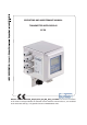
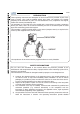

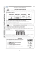
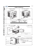
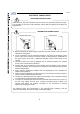

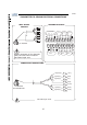
Table Of Contents

SE 56
8
L
(+)
N
(-)
L
N
(+)
(-)
M3
M3
ELECTRICAL CONNECTIONS
GROUNDING INSTRUCTIONS
TRANSMITTER POWER SUPPLY
Com
p
act
/
wall-mount
Panel-mount
ALWAYS ensure that the transmitter and the sensor are grounded (earthed) correctly.
The grounding of the sensor and transmitter ensures that the equipment and liquid are
equipotential.
Before connecting the power supply, verify that the mains voltage is within the limits
indicated on name plate.
For the connections use only approved conductors, with fire-proof properties, whose
section varies from 0.25mm
2
to 2.50mm
2
, based on distance/power; additionally fix
the power supply wires with a additional fastening system located close to the
terminal.
The power supply line must be equipped with an external protection for overload
current (fuse or automatic line breaker).
Provide close to the transmitter a circuit breaker easily accessible for the operator
and clearly identified; whose symbols must conform to the electrical safety and local
electrical requirements.
Ensure that the component complies with the requirements of the standard for
electrical safety distance.
Check chemical compatibility of materials used in the connection security systems in
order to minimize electrochemical corrosion.
The sensor, hardwired inputs and outputs are connected to the transmitter through
a terminal blocks located inside the transmitter.
To locate the compact/wall-mounted version terminal block loosen the 4 screws on
the rear cover. When the front cover is lifted, the terminal block is visible. The
terminal block allows the hardwire connection of the transmitter to external
equipment, including the sensor.
The following pages give informations on the terminal block numbering, and the
respective connecting of the sensor cables, and inputs/outputs.