
Manual

12
4-20 mA output
• Accuracy
• Min. voltage drop at
the device terminals
• Loop impedance
• +/- 1,5% of the full scale
• < 10 V at 20 mA
• max. 100 W at 12 VDC,
max. 700 W at 24 VDC, max.
1000 W at 30 VDC
NPN/PNP output open collector, 50 mA max.
current, frequency up to 600 Hz
Power consumption < 200 mW
English
13
7 ASSEMBLY, INSTALLATION
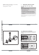
7.1 Assembly of Type 8022
note!
For the fault-free operation of the Type 8022 observe
the following during installation:
• When screwing to the sensor, ensure the seal is seated
correctly.
▶ Torque the screw to a value between 0.2 and 0.3 Nm,
in order not to damage the housing. With a damaged
housing, correct operation cannot be guaranteed.
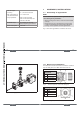
Fig. 1 shows how Type 8022 is screwed to the sensor.
English
14
Fig. 1: Installing Type 8022 on the sensor
English
15
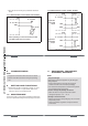
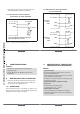
7.2 Electrical Installation
The electrical connection of the device is made on a terminal
strip via cable gland, or an M12 male fixed connector.
Terminal
assignment
1
NPN
2
PNP
3
12 - 30 V DC
4
GND
Fig. 2: Terminal assignment, version with cable gland
Pin assignment
1
12 - 30 V DC
2
NPN
3
GND
4
PNP
Fig. 3: Pin assignment, M12 male fixed connector
English