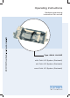
Operating Instructions Bedienungsanleitung Instructions de service Type 8644 AirLINE with Point I/O System (Rockwell) mit Point I/O System (Rockwell) avec Point I/O System (Rockwell)
We reserve the right to make technical changes without notice. Technische Änderungen vorbehalten. Sous resérve de modification techniques. © 2002 Bürkert Werke GmbH & Co.
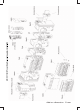
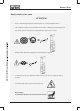
Add-on dimension 11 mm
Add-on dimension 16,5 mm Valves Me03 Rockwell-Field bus node Mp12 Cover plate Cover Me03 Syst Accessories Syst Me03 Syst 6526 6524 Syst 6527 Accessories 0461 Me03 6525
CONTENTS List of contents Type 8644 AirLINE -Rockwell Symbols ..................................................................................................................................................................................................................................................... 4 General safety notes ...................................................................................................................................................................................
CONTENTS SYSTEM DESCRIPTION ......................................................................................................................................................................................................... 17 Bürkert-AirLINE modulare elektrical / pneumatic automation system ................................................................... 19 Valve block (variable configuration) .........................................................................................................
GENERAL NOTES General Notes SYMBOLS .......................................................................................................................................................................................................................................................... 4 GENERAL SAFETY NOTES .............................................................................................................................................................................................
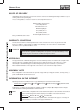
GENERAL NOTES SYMBOLS The following symbols are used in these operating instructions: marks a work step that you must carry out ATTENTION! NOTE marks notes on whose non-observance your health or the functioning of the device will be endangered marks important additional information, tips and recommendations GENERAL SAFETY NOTES Please observe the notes in these operating instructions together with the conditions of use and permitted data that are specified in the data sheet, in order that the device wil
GENERAL NOTES Safety notes for the valve ATTENTION! • Keep to standard engineering rules in planning the use of and operating the device! • Take suitable precautions to prevent inadvertent operation or damage by unauthorized action! • Note that in systems under pressure, piping and valves may not be loosened! 0 bar, psi, kPa • Always switch off the power supply before intervening in the system! • To avoid pressure drop on switching, make the volume of the pressure supply as large as possible! •
GENERAL NOTES SCOPE OF DELIVERY Immediately after receipt of the goods, make sure the contents are undamaged and agree with the scope of delivery stated on the packing slip. In case of irregularities, contact our customer service department at once: Bürkert Fluid Control Systems Service Department Chr.-Bürkert-Str. 13-17 D-76453 Ingelfingen Tel.: (07940) 10-111 Fax: (07940) 10-448 E-mail: info@de.buerkert.
INSTALLATION / COMMISSIONING Installation / Commissioning Installation instructions..................................................................................................................... 8 Illustration of the Valve block ............................................................................................................. 8 Removing the valve block from the top-hat rail ..................................................................................
INSTALLATION / COMMISSIONING Installation instructions The valve block of the AirLINE-system Type 8644 is combined with the Point I/O System from the Rockwell company. Please observe the respective installation notes. ATTENTION! Before starting installation work, switch off the voltage in the vicinity and secure it against being switched on again.
INSTALLATION / COMMISSIONING Removing the valve block from the top-hat rail The valve block is firmly screwed to a standard rail. Additional electrical modules / terminals can be mounted on this. If present, release the adjacent modules / terminals! Unlock the Vavle block from the standard rail by turning the fixing screws anticlockwise as far as they will go. Lift the Valve block vertically from the rail.
INSTALLATION / COMMISSIONING Installation of the AirLINE system (e.g. in a control cabinet) ATTENTION! During work in the control cabinet, observe the relevant safety regulations! Before mounting, check whether the mounting rail is properly anchored in the control cabinet or in the system. Observe the sequence of installation specified in the configuration file(s).
INSTALLATION / COMMISSIONING Fluidic installation Safety notes ATTENTION! The pneumatic connections shall not be pressurized during installation! Make the connections with as large a volume as possible.
INSTALLATION / COMMISSIONING Pneumatic connections - valve units NOTE With 3/2-way valves, the upper ports remain free! Labelling area Service ports with 5/2way valves Service ports with 3/2way valves 8-fold valve unit or 4 / 2-fold valve units Variants 5/2-way valves Variant 1 Variant 2 Variant 3 Service port above (2) M5 M7 D 6, D4, D1/4 Service part below (4) M5 M7 D 6, D4, D1/4 Variant 1 Variant 2 Variant 3 Service port above (0) internally closed off internally closed off internal
INSTALLATION / COMMISSIONING Elektrical installation All the necessary steps for this should be taken from the Rockwell Operating Instructions Chapter 2 „Wiring the Adapter“. Fluidic commissioning Measures to be taken before fluidic initialization Check the connections, voltage and operating pressure! Make sure that the max.
INSTALLATION / COMMISSIONING Special features of commissioning On delivery, all valve islands possess a comparable configuration with regard to module addressing. The first addressable module after the field bus node has the address 62, all following modules the address 63. Reason: If a passive DeviceNet node (1734-PDN) is used, then automatic addressing can only be performed via the modules directly.
MAINTENANCE AND TROUBLESHOOTING Maintenance and troubleshooting TROUBLESHOOTING ..................................................................................................................................................................................................................
MAINTENANCE AND TROUBLESHOOTING TROUBLESHOOTING Fault Possible cause Valves do not switch: Operating voltage not present or insufficient; Remedy Check the electrical connection. Provide operating voltage acc. to nameplate. Valves switch with delay or blow out at the vent connections: Manual override knob not in neutral position; Turn knob to zero position. Pressure supply insufficient or not present.
SYSTEM DESCRIPTION System description MODULAR ELECTRICAL / PNEUMATIC AUTOMATION SYSTEM TYPE 8644 AIRLINE .................................................................................................................................... 19 Features ..................................................................................................................................................................................................................................................................
SYSTEM DESCRIPTION Basic electronic module ME 02 / 8-fold 2 x monostable .......................................................................................................................... 46 Basic electronic module ME03 / 2-fold monostable ........................................................................................................................................ 47 Basic electronic module ME03 / 4-fold monostable ..........................................................................
SYSTEM DESCRIPTION MODULAR ELECTIRCAL / PENUMATIC AUTOMATION SYSTEM TYPE 8644 AirLINE AirLINE Type 8644 is an electrical and pneumatic automation system which has been developed for use in control cabinets or boxes. In a through system, all electronic and pneumatic components are standardized so that if simple rules are complied with, electrical and electronic modules of differing functionality may be combined in a very simple manner. All components are connected via a snap-on mechanism.
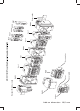
SYSTEM DESCRIPTION System structure Schematic representation of the Bürkert AirLine system Illustration of the valve block Connector module left Manometer for indication of operating pressure at the station 8-fold valve unit Intermediate supply 2-fold valve unit Connector module right Supply and exhaust ports Service ports Supply and exhaust ports Service ports Illustration of the modules of the Bürkert AirLine system 20 - 8644/Rockwell Supply and exhaust ports
SYSTEM DESCRIPTION System description In its minimal configuration, the system consists of field bus nodes and the valve block. The closing plate protects both the system and persons from improper contact. Terminals can be arranged before and after the valve block.
SYSTEM DESCRIPTION VALVE BLOCK The valve block is composed of the following modules: Connector module left Electrical interface Supply unit right Intermediate supply 2-fold valve units 8-fold valve units 2-fold valve units Supply units left Connector modules/supply units (collective ports for supply, exhaust and auxiliary control air) Valve units (service ports, miscellaneous vales) Electrical interface • • Connector module right Example of a valve block, schematic Viewed from the outside, th
SYSTEM DESCRIPTION VALVE UNITS Construction Valve units are of modular construction and consist of: • • • Basic electronic modules Basic pneumatic modules Valves Valves Basic electronic module Service ports (outputs) Basic pneumatic module Modular construction of the valve units The digital outputs, on which the valves sit, are switched on the basic electronic module. Depending ont he function, these switch the internal P channel to the service ports (outputs) of the pneumatic module.
ATTENTION! 24 - 8644/Rockwell 0,9 W 1W Power 2 ... 10 bar - 700 I/min Dependent on the connection technology, the expansion stage and the control. 3 according to VDE 0580 * 3 x 10 mm valves for istallation dimension 16.5 mm ** max.
SYSTEM DESCRIPTION Technical data for the overall system Voltage supply: Rated voltage Tolerance Valve types 0460, 0461 Valve type 6524 (2x 3/2-way) 24 V/DC - 15% / + 20% - 10% / + 10% - 15% / + 10% Current carrying capacity: Logic area 24 V area 1A 2.5 A Maximum current consumption: I_module proportion of current in the logic area of the basic electronic modules max.
SYSTEM DESCRIPTION CONNECTOR MODULES 3 1 Structure of the connector module 4 12 2 11 6 (7) (8) (10) 5 11 (9) 8+9 Structure of the connector module 7 10 No.
SYSTEM DESCRIPTION Variants The supply units have been designed in various variants to take account of differing requirements. For simple commissioning and diagnosis, supply units are available with a manometer. You can obtain the fluidic connections with straight or conical screw connections as well as with fast coupling systems. For special functions the fluidic connections may be used for different purposes, e.g.
SYSTEM DESCRIPTION Connector modules, pneumatic - left, type ME02 Variants Supply port (P) 1 Connection X Exhaust port (R/S) 3/5 without manometer G¼ M5 G¼ D 10 D4 D 10 NPT ¼ M5 NPT ¼ with manometer G¼ M5 G¼ D 10 D4 D 10 NPT ¼ M5 NPT ¼ Connection X Operating mode Configuration of X Standard Exhaust air from pilot valve Auxiliary control air Connection for auxiliary control air Operation with auxiliary control air is optional Drawing showing variants End supply unit left Cover Ma
SYSTEM DESCRIPTION Technical data Housing dimensions (width x height x depth) 61 mm x 71 mm x 130 mm (incl. snap-on hooks) Weight 220 g Permissible temperature (storage/transport) -20 °C to +60 °C Permissible air humidity 75% mean, 85% occasionally ATTENTION! In the range of 0 to +55 °C, suitable precautions must be taken against elevated humidity (> 85%). Slight condensation of short duration on the outside of the housing is permissible, e.g.
SYSTEM DESCRIPTION Conector modules, pneumatic - left, type ME03 Variants Supply port (P) 1 Connection X Exhaust port (R/S) 3/5 without manometer G 3/8 G 1/8 G 3/8 NPT 3/8 NPT 1/8 NPT 3/8 with manometer G 3/8 G 1/8 G 3/8 NPT 3/8 NPT1/8 NPT 3/8 Connection X Operating mode Configuration of X Standard Exhaust air from pilot valve Auxiliary control air Connection for auxiliary control air Operation with auxiliary control air is optional Drawing showing variants End supply unit left Cover
SYSTEM DESCRIPTION Technical data Housing dimensions (width x height x depth) 78 mm x 93 mm x 143 mm (incl. snap-on hooks) Weight 400 g Permissible temperature (storage/transport) -20 °C to +60 °C Permissible air humidity 75% mean, 85% occasionally ATTENTION! In the range of 0 to +55 °C, suitable precautions must be taken against elevated humidity (> 85%). Slight condensation of short duration on the outside of the housing is permissible, e.g.
SYSTEM DESCRIPTION Connector modules, pneumatic - middle, type ME02 Variants Supply port (P) 1 Connection X Exhaust port (R/S) 3/5 without manometer G¼ M5 G¼ D 10 D4 D 10 NPT ¼ M5 NPT ¼ with manometer G¼ M5 G¼ D 10 D4 D 10 NPT ¼ M5 NPT ¼ Connection X Operating mode Configuration of X Standard Exhaust air from pilot valve Auxiliary control air Connection for auxiliary control air Operation with auxiliary control air is optional Drawing showing variants Intermediate supply Cover M
SYSTEM DESCRIPTION Technical data Housing dimensions (width x height x depth) 52 mm x 71 mm x 119 mm (incl. snap-on hooks) Weight 118 g Permissible temperature (storage/transport) -20 °C to +60 °C Permissible air humidity 75% mean, 85% occasionally ATTENTION! In the range of 0 to +55 °C, suitable precautions must be taken against elevated humidity (> 85%). Slight condensation of short duration on the outside of the housing is permissible, e.g.
SYSTEM DESCRIPTION Connector modules, pneumatic - middle, TYPE ME03 Variants Supply port (P) 1 Connection X Exhaust port (R/S) 3/5 without manometer G 3/8 G 1/8 G 3/8 NPT 3/8 NPT 1/8 NPT 3/8 with manometer G 3/8 G 1/8 G 3/8 NPT 3/8 NPT1/8 NPT 3/8 Connection X Operating mode Configuration of X Standard Exhaust air from pilot valve Auxiliary control air Connection for auxiliary control air Operation with auxiliary control air is optional Drawing showing variants Intermediate supply Cover
SYSTEM DESCRIPTION Technical data Housing dimensions (width x height x depth) 66 mm x 93 mm x 142 mm (incl. snap-on hooks) Weight 335 g Permissible temperature (storage/transport) -20 °C to +60 °C Permissible air humidity 75% mean, 85% occasionally ATTENTION! In the range of 0 to +55 °C, suitable precautions must be taken against elevated humidity (> 85%). Slight condensation of short duration on the outside of the housing is permissible, e.g.
SYSTEM DESCRIPTION Connector modules, pneumatic - right, type ME02 Variants Supply port (P) 1 Connection X Exhaust port (R/S) 3/5 without manometer G¼ M5 G¼ D 10 D4 D 10 NPT ¼ M5 NPT ¼ with manometer G¼ M5 G¼ D 10 D4 D 10 NPT ¼ M5 NPT ¼ Connection X Operating mode Configuration of X Standard Exhaust air from pilot valve Auxiliary control air Connection for auxiliary control air Operation with auxiliary control air is optional Drawing showing variants End supply unit right Manomet
SYSTEM DESCRIPTION Technical data Housing dimensions (width x height x depth) 61 mm x 71 mm x 130 mm Weight 220 g Permissible temperature (storage/transport) -20 °C to +60 °C Permissible air humidity 75% mean, 85% occasionally ATTENTION! In the range of 0 to +55 °C, suitable precautions must be taken against elevated humidity (> 85%). Slight condensation of short duration on the outside of the housing is permissible, e.g. when the terminal is brought from a vehicle into a closed room.
SYSTEM DESCRIPTION Connector modules, pneumatic - right, type ME03 Variants Supply port (P) 1 Connection X Exhaust port (R/S) 3/5 without manometer G 3/8 G 1/8 G 3/8 NPT 3/8 NPT 1/8 NPT 3/8 with manometer G 3/8 G 1/8 G 3/8 NPT 3/8 NPT1/8 NPT 3/8 Connection X Operating mode Configuration of X Standard Exhaust air from pilot valve Auxiliary control air Connection for auxiliary control air Operation with auxiliary control air is optional Drawing showing variants End supply unit right Mano
SYSTEM DESCRIPTION Technical data Housing dimensions (width x height x depth) 63 mm x 93 mm x 143 mm Weight 390 g Permissible temperature (storage/transport) -20 °C to +60 °C Permissible air humidity 75% mean, 85% occasionally ATTENTION! In the range of 0 to +55 °C, suitable precautions must be taken against elevated humidity (> 85%). Slight condensation of short duration on the outside of the housing is permissible, e.g. when the terminal is brought from a vehicle into a closed room.
SYSTEM DESCRIPTION BASIC ELECTRONIC MODULES Functional module LED display General description The basic electronic module is connected to the adjacent modules via its electrical interface. In this way it receives both voltage supply and control signals for the valves on the plug-on positions. The basic electronic modules and hences the valve units may be controlled as digital output modules/terminals. More detailled information is to be found in the chapter Commissioning.
SYSTEM DESCRIPTION Basic electronic module ME02 / 2-fold monostable Construction An electric base module consists of a distribution module (backplane bus) and a function module. The two modules are connected by a 14-pin board-to-board plug.
SYSTEM DESCRIPTION Basic electronic module ME02 / 8-fold monostable Construction A basic electronic module consists of a distributor module (back-wall bus) and a function module. Both modules are contacted via a 14-pole board-to-board connector.
SYSTEM DESCRIPTION Basic electronic module ME02 / 2-fold bistable Construction A basic electronic module consists of a distributor module (back-wall bus) and a function module. Both modules are contacted via a 14-pole board-to-board connector.
SYSTEM DESCRIPTION Basic electronic module ME02 / 2-fold 2 x monostable Construction An electric base module consists of a distribution module (backplane bus) and a function module. The two modules are connected by a 14-pin board-to-board plug.
SYSTEM DESCRIPTION Basic electronic module ME02 / 8-fold bistable Construction An electric base module consists of a distribution module (backplane bus) and a function module. The two modules are connected by a 14-pin board-to-board plug.
SYSTEM DESCRIPTION Basic electronic module ME02 / 8-fold 2x monostable Construction An electric base module consists of a distribution module (backplane bus) and a function module. The two modules are connected by a 14-pin board-to-board plug.
SYSTEM DESCRIPTION Basic electronic module ME03 / 2-fold monostable Construction A basic electronic module consists of a distributor module (back-wall bus) and a function module. Both modules are contacted via a 14-pole board-to-board connector.
SYSTEM DESCRIPTION Basic electronic module ME03 / 4-fold monostable Construction A basic electronic module consists of a distributor module (back-wall bus) and a function module. Both modules are contacted via a 14-pole board-to-board connector.
SYSTEM DESCRIPTION Basic electronic module ME03 / 3-fold 10 mm monostable Construction A basic electronic module consists of a distributor module (back-wall bus) and a function module. Both modules are contacted via a 14-pole board-to-board connector.
SYSTEM DESCRIPTION Basic electronic module ME03 / 2-fold bistable Construction A basic electronic module consists of a distributor module (back-wall bus) and a function module. Both modules are contacted via a 14-pole board-to-board connector.
SYSTEM DESCRIPTION BASIC PNEUMATIC MODULE General description On the basic pneumatic module are to be found the service ports for subsequent applications. Several basic modules may be built up in a row by interlocking. Sealing from the outside is maintained. By unsing a bulkhead fitting, the P port may be sealed. Thus different working pressures can coexist in one valve block.
SYSTEM DESCRIPTION Basic pneumatic module with integral pressure shut-off General description For the basic pneumatic module MP 11 in the 2-way and 8-way versions, an integral pressure shut-off is available as an option. With this option, a faulty valve may be exchanged under pressure without relieving the pressure in the entire valve island or system. On exchange of the valve, the open cross section is reduced by a mechanism until only a very small leak remains.
SYSTEM DESCRIPTION Valves Types 6524 (2 x 3/2-way) / 6524 / 6525 Type 6526 / 6527 Type 0460 / 0461 EEx approval II 3 G EEx nA II T4 for the Types 6524 / 6525 [Exception Type 6524 (2x 3/2-way)]. General description Automation systems are increasingly used in all areas where control duties are to be performed. The valves thereby form the interface between electronics and pneumatics. The valves consist of a pilot solenoid valve and a pneumatic valve.
SYSTEM DESCRIPTION Variants With AirLINE Type 8644, valves with the following circuit functions may be integrated: Valves Circuit function 3/2-way C (NC) Actuation Width Type internal control air 10 6524 16 6526 10 6525 16 6527 10 0460 16 0461 10 0460 16 0461 D (NO) C (NC) auxiliary control air D (NO) C-vaccum (NC) 2 x 2/3-way 3/2-way 2 x C (NC) internal control air 2 x C (NC) auxiliary control air C (NC) internal control air D (NO) C (NC) auxiliary control air D (NO) C-
SYSTEM DESCRIPTION Limitations for use in Zone 2 ATTENTION! For valve types 6526 and 6527, for use in Zone 2 with temperature class T4, the limitation (valve switch-off time) TOFF ≥ 0.
SYSTEM DESCRIPTION NOTES 56 - 8644/Rockwell
APPENDIX APPENDIX EC-Declaration of Conformity .............................................................................................................................................................................................. A2 Certificate of Conformity ...............................................................................................................................................................................................................
APPENDIX EC DECLARATION OF CONFORMITY Bürkert Werke GmbH & Co. KG hereby declares as the manufacturer that these products comply with the requirements listed in the Guidelines of the Council for Harmonization of the Regulation of the Member States. in respect of electromagnetic compatibility (89/336/EEC) and are stipulated for devices and protective systems for intended use in potentially explosive zones (ATEX, 94/9EC).
APPENDIX 8644/Rockwell - A3
APPENDIX A4 - 8644/Rockwell
Contact addresses / Kontaktadressen Germany / Deutschland / Allemange Bürkert Fluid Control System Sales Centre Chr.-Bürkert-Str. 13-17 D-74653 Ingelfingen Tel. + 49 (0) 7940 - 10 91 111 Fax + 49 (0) 7940 - 10 91 448 E-mail: info@de.buerkert.com International Contact addresses can be found on the internet at: Die Kontaktadressen finden Sie im Internet unter: Les adresses se trouvent sur internet sous : www.burkert.
The smart choice of Fluid Control Systems www.buerkert.