IN S TAL L AT ION , OP E R AT IN G AN D S E R V IC E IN S T R U C T ION S F OR S E R IE S 8H GA S - F I R E D BOI L E R 3050579 F o r s e rvi c e o r re p a i rs to b o i le r, c a ll yo ur he a ti ng c o ntra c to r. Whe n s e e k i ng i nfo rma ti o n o n b o i le r, p ro vi d e B o i le r Mo d e l Numb e r a nd S e ri a l Numb e r a s s ho wn o n Ra ti ng L a b e l.
IMPORTANT INFORMATION - READ CAREFULLY NOTE: The equipment must be installed in accordance with those installation regulations enforced in the area where the installation is to be made. These regulations shall be carefully followed in all cases. Authorities having jurisdiction shall be consulted before installations are made. All wiring on boilers installed in the USA shall be made in accordance with the National Electrical Code and/or local regulations.
WARNING This boiler requires regular maintenance and service to operate safely. Follow the instructions contained in this manual. Improper installation, adjustment, alteration, service or maintenance can cause property damage, personal injury or loss of life. Read and understand the entire manual before attempting installation, start-up operation, or service. Installation and service must be performed only by an knowledgeable, experienced, and skilled installer or service agency.
Table of Contents I. Pre-Installation..............................................................6 II. Boiler Assembly............................................................8 III. Gas Control System Assembly...................................15 (Knockdown Boilers) IV. Water Trim and Piping................................................25 V. Gas Piping...................................................................29 VI. Venting..................................................................
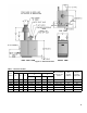
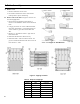
Figure 1: Dimensional Data Table 1: Dimensional Data Dimensions (Inches) Boiler Model A B C 805H 20 10 806H 23-3/4 807H 27-1/2 808H 31-1/4 809H 35 810H 38-3/4 D E Recommended Chimney Size (Round) Water Content (Gallons) Approx. Shipping Weight (LB.) USA Canada USA Canada 7 24-13/16 24-13/16 16-1/8 16-1/8 7” dia. x 15 ft. 11.9 705 11-7/8 8 27-13/16 25-3/4 18 16 8” dia. x 15 ft. 13.9 785 13-3/4 9 28-13/16 25-3/4 18 16 8” dia. x 15 ft. 15.
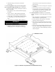
I. Pre-Installation WARNING Carefully read all instructions before installing boiler. Failure to follow all instructions in proper order can cause personal injury or death. A. Inspect shipment carefully for any signs of damage. All equipment is carefully manufactured, inspected and packed. Our responsibility ceases upon delivery of boiler to carrier in good condition. Any claim for damage or shortage in shipment must be filed immediately against carrier by consignee.
b. If result is less than 50 ft3 per 1,000 Btuh, space is considered a confined space. 4. Determine building type. A building of unusually tight construction has the following characteristics: a. Walls and ceiling exposed to outside atmosphere have a continuous water vapor retarder with a rating of 1 perm or less with openings gasketed and sealed, and b. Weather-stripping has been added on openable windows and doors, and c.
II. Boiler Assembly A. Remove Crate 1. Remove all fasteners at crate skid. 2. Lift outside container and remove with all other inside protective spacers and bracing. B. Remove boiler from skid. See Figure 2. Exercise care to avoid dropping boiler. 1. Place boiler in approximate location. Refer to Section I: Pre-Installation. Remove base hold down bolts. 2. Using pry bar under rear corner of Base End Panel, raise boiler and install 1½” wood blocks under rear corners.
6. Lift boiler with pry bar. Remove wood blocks. Lower boiler. C. For Packaged Boiler only, proceed to Paragraph E. D. Test Section Assembly for leaks before connecting to system and installing controls, trim and jacket. Refer to Figure 3 and Table 3. 1. Plug Tappings C & E (¾ NPT) and Return Tapping B (2 NPT). 2. Insert ¾” NPT x ¼” NPT bushing in Tapping D. Install pressure gauge capable of indicating 50 psi. 3. Insert 2” NPT x ¾” NPT bushing in Supply Tapping A.
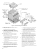
Figure 5: General Assembly (Knockdown Boilers) F. Move boiler to permanent location by sliding or walking. Do not drop. For Packaged Boiler, proceed to Paragraph L. G. Confirm that one (1) Flue Baffle is properly positioned in each Boiler Flueway. Tabs at the top of each Flue Baffle should be resting on top row of Flue Pins on each adjoining section. H. Install Canopy on section assembly. See Figure 5. Canopy and hardware are located in Combination Boiler Parts and Control Carton. 1.
Figure 6: Flame Roll-out Switch Installation Figure 7: Burner/Burner Access Panel Installation 11
M. Attach Flame Roll-out Switch to Burner Access Panel. See Figure 6. Flame Roll-out Switch and hardware are located in Combination Boiler Parts and Control Carton. Flame Roll-out Switch is a single use device - do not test with heat - switch cannot be reset. 1. Cut insulation from semicircular notch at right end of the burner access panel. Models 808H - 810H have two (2) burner access panels. Remove insulation from notch of right side burner access panel only. 2.
Figure 8: Jacket Assembly
Figure 9: EP/OP Control Installation 14
III. Gas Control System Assembly (Knockdown Boilers) A. 24V Standing Pilot Control System Install Gas Control System. All components are located in Combination Boiler Parts and Control Carton. 1. Install Gas Control Assembly on Manifold. See Figure 10. Use thread (joint) compound (pipe dope) resistant to action of liquefied petroleum gas. 2. Install pilot burner piping and controls. See Figure 10. 3. Connect Thermocouple Lead to Gas Valve. 4.
F. EP-CSD-1 Control System Install Gas Control System. All components are located in Combination Boiler Parts and Control Carton. 1. Install Gas Control Assembly on Manifold. See Figure 17. 2. Install pilot burner piping and controls. See Figure 17. 3. Install Ignition Transformer. a. Attach Ignition Transformer to Jacket Vestibule Panel using four (4) #8 x ½” lg. sheet metal screws. 16 b. Connect Ignition Lead from Pilot to Ignition Transformer. 4.
Figure 10: Schematic Gas Piping, 24V Standing Pilot, 806H & 807H
Figure 11: Main Gas Piping, Intermittent Ignition (EI)
Figure 12: Schematic Pilot Piping (Honeywell EI), USA
Figure 13: Schematic Pilot Piping (Honeywell EI) Canada: Natural Gas, 805H - 810H; LP Gas, 806H - 807H
Figure 14: Schematic Gas Piping, OP Control System, 806H - 810H
Figure 15: Schematic Gas Piping, OP-CSD-1 Control System, 808H - 810H
Figure 16: Schematic Gas Piping, EP Control System (Natural Gas Only), 806H - 810H
Figure 17: Schematic Gas Piping, EP-CSD-1 Control System, 808H - 810H
IV. Water Trim and Piping WARNING Failure to properly pipe boiler may result in improper operation and damage to boiler or structure. Oxygen contamination of boiler water will cause corrosion of iron and steel boiler components, and can lead to boiler failure. Burnham’s Warranty does not cover problems caused by oxygen contamination of boiler water or scale (lime) build-up caused by frequent addition of water. A.
Figure 19: Drain Piping Installation D. Install Drain Valve in rear of Left End Section, Tapping “G”. See Figure 19. Components are located in Water Trim Carton. E. Install Temperature-Pressure Gauge. Components are located in Water Trim Carton. 1. Standard Temperature - Pressure Gauge Piping. See Figure 20. Figure 21: Alternate Temperature-Pressure Gauge Installation b. Install 2 NPT x ¾ NPT x 2 NPT Tee (provided) or 2 NPT x 2 NPT x ¾ NPT Tee (installer furnished). ¾ NPT leg should face forward. c.
2. If boiler is connected to heating coils located in air handling units where they may be exposed to refrigerated air, boiler piping must be equipped with flow control valves to prevent gravity circulation of boiler water during cooling system operation. 3. The piping diagrams shown (Figure 23, Detail “A” and Detail “B”) are recommended for optimum operation and long term reliability.
a. A boiler by-pass is recommended for any installation for improved system temperature balance, while serving to protect the boiler from sustained condensing operation. The by-pass also provides some measure of low return water temperature protection by reducing flow through the boiler. See Figure 23. b.
V. Gas Piping 4. Specific gravity of gas. Gas piping systems for gas with a specific gravity of 0.70 or less can be sized directly from Table 6, unless authority having jurisdiction specifies a gravity factor be applied. For specific gravity greater than 0.70, apply gravity factor from Table 8. If exact specific gravity is not shown choose next higher value. For materials or conditions other than those listed above, refer to the National Fuel Gas Code, NFPA 54/ANSI Z223.1 and/or CAN/CSA B149.
Table 6: Maximum Capacity of Schedule 40 Pipe in CFH for Gas Pressures of 0.5 psig or Less Length (Feet) ½ 0.3 Inch w.c. Pressure Drop ¾ 1 1¼ ½ 0.5 Inch w.c.
VI. Venting A. Install vent system in accordance with local building codes; or local authority having jurisdiction; or National Fuel Gas Code, ANSI Z223.1/NFPA 54, Part 7, Venting of Equipment and/or CAN/CSA B149.1, Venting Systems and Air Supply for Appliances. Install any of the following for this Series 8H Category I, draft hood equipped appliance: 1. Type B or Type L gas vent. Install in accordance with listing and manufacturer’s instructions. 2. Masonry or metal chimney.
E. Boiler Equipped With Vent Damper. See Figure 26. 1. Open Vent Damper Carton and remove Installation Instructions. Read Installation Instructions thoroughly before proceeding. CAUTION Do not use one vent damper to control two or more heating appliances. 2. Vent damper must be same size as draft hood outlet. See Figure 1. Unpack vent damper carefully. Forcing vent damper open or closed may damage gear train and void warranty. Vent damper assembly includes pre-wired connection harness with polarized plug.
9. Design vent system for sea level input. venting system are located and other spaces of the building. Turn on clothes dryers and any appliance not connected to the common venting system. Turn on any exhaust fans, such as range-hoods and bathroom exhausts, so they will operate at maximum speed. Do not operate a summer exhaust fan. Close fireplace dampers. 10. Provide adequate ventilation of Boiler Room. See Section I: Pre-Installation. 11.
VII. Electrical DANGER Positively assure all electrical connections are unpowered before attempting installation or service of electrical components or connections of the boiler or building. Lock out all electrical boxes with padlock once power is turned off. WARNING Failure to properly wire electrical connections to the boiler may result in serious physical harm. Electrical power may be from more than one source. Make sure all power is off before attempting any electrical work.
E. Alliance SL™ Water Heater (if used). May be used through Terminal 2 and the damper motor is deenergized. with Intermittent Circulation only. 5. When the call for heat is satisfied, the damper relay coil is de-energized - closing contacts which energize the damper motor. This causes the damper to close. When the damper blade reaches the fully closed position, the damper motor is de-energized.
Table 10: Sequence of Operation and Wiring Diagrams Ignition System Country Fuel Standing Pilot (24V) USA & Canada Natural Gas Standing Pilot (OP - 120V) USA & Canada Natural Gas Standing Pilot (OP-CSD-1 - 120V USA LP Gas USA Intermittent Ignition (Honeywell EI - 24V) Canada LP Gas LP Gas Natural Gas LP Gas Intermittent 6 & 7 Sect. Figure 29 Figure 30 Page 36 6 - 10 Sect. Figure 31 Figure 32 Page 39 8 - 10 Sec. Figure 31 Figure 32 Page 39 5 - 10 Sect.
Figure 29: Wiring Diagram, Standing Pilot (24V), USA and Canada, Continuous Circulation 37
Figure 30: Wiring Diagram, Standing Pilot (24V), USA and Canada, Intermittent Circulation
2. Electronically Supervised Standing Pilot (OP) Sequence of Operation 3. Electronically Supervised Standing Pilot (OP-CSD-1) Sequence of Operation a. Normal Operation i. Thermostat or operating control calls for heat. ii. Terminal #6 of RM7890C Burner Control is energized, initiating a microcomputer monitored circuit test. iii. Pilot Flame Establishing Period (PFEP) begins. iv. After pilot flame is proven, terminal #9 of RM7890C is energized, allowing main gas flow and ignition of main burners.
Figure 31: Wiring Diagram, OP/OP-CSD-1 Ignition System, Continuous Circulation
Figure 32: Wiring Diagram, OP/OP-CSD-1 Ignition System, Intermittent Circulation 41
4. Honeywell EI Sequence of Operation a. Normal Operation i. Thermostat or operating control calls for heat. Vent Damper (if used) opens. ii. Ignition Module Terminals PV, MV/PV and the Ignition Terminal are energized. Terminals PV and MV/PV power the Pilot Valve in the Gas Valve supplying gas to the Pilot. The Ignition Terminal supplies voltage to the Ignition Electrode creating an electric spark to ignite the Pilot. iii.
Figure 33: Wiring Diagram, Honeywell EI, USA, Continuous Circulation 43
Figure 34: Wiring Diagram, Honeywell EI, USA, Intermittent Circulation
Figure 35: Wiring Diagram, Honeywell EI, Canada, Continuous Circulation 45
Figure 36: Wiring Diagram, Honeywell EI, Canada, Intermittent Circulation
6. Electronically Supervised Intermittent Ignition (EP/EP-CSD-1) Sequence of Operation a. Normal Operation i. Thermostat or operating control calls for heat. ii. Terminal #6 of RM7890A Burner Control is energized, initiating a microcomputer monitored circuit test. iii. The pilot valve (terminal 8) and ignition transformer (terminal 10) are energized. The pilot valve opens and the ignition electrode sparks, igniting the pilot. iv.
Figure 37: Wiring Diagram, EP/EP-CSD-1 Ignition System, USA, Continuous Circulation
Figure 38: Wiring Diagram, EP/EP-CSD-1 Ignition System, USA, Intermittent Circulation 49
Figure 39: McDonnell & Miller 750P-MT (120V) L.W.C.O. Wiring for Boilers with 24V Limit Circuits Figure 40: McDonnell & Miller 750P-MT (120V) L.W.C.O.
Figure 41: Hydrolevel OEM - 170/550/650/750 (120V) L.W.C.O. Wiring for Boilers with 24V Limit Circuits Figure 42: Hydrolevel OEM - 170/550/650/750 (120V) L.W.C.O.
VIII. System Start-Up WARNING Completely read, understand and follow all instructions in this manual before attempting start-up. A. Safe operation and other performance criteria were met with the gas manifold and control assembly provided on boiler when boiler underwent tests specified in American National Standard for Gas-Fired LowPressure Steam and Hot Water Boilers, ANSI Z21.13. B. Check Main Burners.
Figure 43: Lighting Instructions (24V Standing Pilot) 53
Figure 44: Operating Instructions (EI) 54
Figure 45: Lighting Instructions (OP) 55
Figure 46: Operating Instructions (EP) 56
BOILER OPERATING INSTRUCTIONS TO SHUT DOWN: 1. Close manual main shut-off valve(s) and pilot valve(s). 2. Turn off main electric switch. TO START UP: 1. Make sure that both the main manual and the pilot valve(s) have been off for at least five minutes. 2. Turn room thermostat and all operating controls to lowest setting. 3. Remove burner access panel(s). 4. Open manual pilot valve(s). NOTE: Item (5) applies only to boilers with standing pilot safety switch(es). 5.
Figure 48: Honeywell Q314 Pilot Flame (24V Standing Pilot) Figure 50: Honeywell Q179D Pilot Flame (OP) Figure 51: Honeywell Q179C Pilot Flame (EP) Figure 49: Honeywell Q348 Pilot Flame (24V Electronic Ignition) I. Check pilot burner flame and main burner flames through observation port. 1. Check pilot flame. Refer to Table 11 for appropriate pilot detail. 2. Adjust thermostat to highest setting. 3. Check main burner flames. See Figure 52.
CAUTION Avoid operating this boiler in an environment where saw dust, loose insulation fibers, dry wall dust, etc. are present. If boiler is operated under these conditions, the burner interior and ports must be cleaned and inspected daily to insure proper operation. 3. Clock gas meter for at least 30 seconds. Use Table 12 to determine gas flow rate in Cubic Feet per Hour. Table 12: Input Rate Size of Gas Meter Dial Seconds for One One-Half One Two Five Revolution Cu. Ft. Cu. Ft. Cu. Ft. Cu. Ft.
b. Increase input rate if less than 98% of rating plate input. Increase manifold gas pressure no more than 0.3 inch w.c. If measured input rate is still less than 98% of rated input: i. Remove Main Burners per procedure in Section IX: Service. ii. Remove gas orifices. Drill one (1) drill size larger (drill size is stamped on orifice, or see Key No. 4E). iii. Reinstall gas orifices and main burners. Measure input rate. 6. Recheck Main Burner Flame. 7.
IX. Service WARNING Service on this boiler should be undertaken only by trained and skilled personnel from a qualified service agency. Inspections should be performed at intervals specified in this manual. Maintain manual in a legible condition. Keep boiler area clear and free of combustible materials, gasoline and other flammable vapors and liquids. Do not place any obstructions in boiler room that will hinder flow of combustion and ventilation air.
Important Product Safety Information Refractory Ceramic Fiber Product Warning: The Repair Parts list designates parts that contain refractory ceramic fibers (RCF). RCF has been classified as a possible human carcinogen. When exposed to temperatures about 1805°F, such as during direct flame contact, RCF changes into crystalline silica, a known carcinogen. When disturbed as a result of servicing or repair, these substances become airborne and, if inhaled, may be hazardous to your health.
Figure 53: Boiler Flueway Cleaning F. Clean Combustion Chamber by vacuuming. Exercise care to avoid damaging Base Insulation. G. Install Burners by reversing procedures used to remove burners. Verify Main Burners are properly located on support bracket in Base Rear Panel, seated on Main Burner Orifices, and secured with hitch pin clips. Verify Main Burner with Pilot Bracket is in proper location. See Table 13. H. Lubrication.
Honeywell EI Ignition Module Yellow LED Flame Codes Yellow LED Flash Codea Indicates Recommended Service Action Heartbeat Normal Flame Signal N/A 2 Weak Flame Signal System will operate reliably but flame signal is less than desired. Note: This indication may flash temporarily during or shortly after lightoff on some applications. Perform routine maintenance to assure optimum flame signal. 1 Marginal Flame Signal (less than 1.1 µA) System may not operate reliably over time.
Honeywell EI Ignition Module Green LED Status Codes Green LED Flash Code (X + Y)a Next System Action Recommended Service Action No “Call for Heat” N/A None Flash Fast Startup - Flame sense calibration N/A None Heartbeat Normal operation N/A None OFF If system fails to light on next trial for ignition check gas supply, pilot burner, spark and flame sense wiring, flame rod contamination or out of position, burner ground connection.
Honeywell EI Trouble Shooting Guide 66
X. Repair Parts All Series 8H Repair Parts may be obtained through your local Burnham Wholesale distributor. Should you require assistance in locating a Burnham Distributor in your area, or have questions regarding the availability of Burnham products or repair parts, please contact Burnham Customer Service at: (717) 481-8400 or Fax (717) 481-8408.
Item No. Description Part No. Quantity 805H 806H 807H 808H 809H 810H 6171605 1 --- --- --- --- --- 6171606 --- 1 --- --- --- --- 6171607 --- --- 1 --- --- --- 6171608 --- --- --- 1 --- --- 6171609 --- --- --- --- 1 --- 1.
Item No. Description Part No. Quantity 805H 806H 807H 808H 809H 810H 6111605 1 --- --- --- --- --- 6111606 --- 1 --- --- --- --- 6111607 --- --- 1 --- --- --- 6111608 --- --- --- 1 --- --- 6111609 --- --- --- --- 1 --- 6111610 --- --- --- --- --- 1 2.
Item No. Description Part No.
Item No. Description Part No. Quantity 805H 806H 807H 808H 809H 810H 4.
Item No. Description Part No.
Item No. Description Part No.
Item No. Description Part No. Size Gas Valve, Robertshaw 7000DERHC, Natural Gas, 1” NPT 81660151 805H-810H Gas Valve, Robertshaw 7000DERHC-LP, LP Gas, 1” NPT 81660158 USA: 805H-810H Canada: 805H-807H Quantity 5-3 Gas Train -- Intermittent Ignition (EI) USA: 5 - 10 Section, Natural and LP Gas Canada: 5 - 10 Section, Natural Gas 5 - 7 Section, LP Gas A B Lubricated Manual Shut-Off Valve, Newman-Milliken 200M, 1” NPT C Nipple, 1’ NPT x 2” Lg.
Item No. Description Part No.
Item No. Description Part No.
Item No. Description Part No. Size Quantity 5-6 Pilot Assembly and Piping -- Standing Pilot (24V) USA & Canada: 6 & 7 Section, Natural and LP Gas Pilot Burner, Honeywell Q314A3687, Natural Gas 8236033 Pilot Burner, Honeywell Q314A3828, LP Gas 8236034 B Thermocouple, Honeywell Q309A1996 w/36” Lg.
Item No. Description Part No. Size Quantity 5-7 Pilot Assembly and Piping -- Intermittent Ignition (Honeywell EI) USA 5 - 10 Section, Natural and LP Gas A 78 Pilot Burner, Honeywell Q348A1002, Natural Gas 8236072U Pilot Burner, Honeywell Q348A1010, LP Gas 8236081 1 B Igniter/Sensor Cable, 36” Lg.
Item No. Description Part No. Size Quantity 5-8 Pilot Assembly and Piping -- Intermittent Ignition (Honeywell EI) Canada 5 - 10 Section, Natural Gas 5 - 7 Section, LP Gas 8236072U 805H-810H Pilot Burner, Honeywell Q348A1010, LP Gas 8236081 805H-807H B Igniter/Sensor Cable, 36” Lg.
Item No. Description Part No. Size Quantity 806H-810H 1 5-9 Pilot Assembly and Piping -- Standing Pilot (OP) USA & Canada: 6 - 10 Section, Natural and LP Gas A 8236025 Pilot Burner, Honeywell Q179D1008 w/388146KD Orifice, LP Gas 6236039 B Thermocouple, Honeywell Q309A1996 w/36” Lg. Lead 8236004 C Flame Rod Lead, Honeywell R1298020, 4 Ft. Lg.
Item No. Description Part No. Size Quantity 5-10 Pilot Assembly and Piping -- Standing Pilot (OP-CSD-1) USA Only: 8 - 10 Section, LP Gas Only A Pilot Burner, Honeywell Q179D1008 w/388146KD Orifice, LP Gas 6236039 1 B Thermocouple, Honeywell Q309A1996 w/36” Lg. Lead 8236004 1 C Flame Rod Lead, Honeywell R1298020, 4 Ft. Lg.
Item No. Description Part No. Size Quantity 5-11 Pilot Assembly and Piping -- Intermittent Ignition (EP) USA & Canada: 6 - 10 Section, Natural Gas Only A Pilot Burner, Honeywell Q179C1009, Natural Gas 8236017 1 B Flame Rod Lead, Honeywell R1298020, 4 Ft. Lg. 71362561 1 C Rajah Connector, Honeywell 37356 8236021 D Ignition Lead, Honeywell R1061012, 3 Ft. Lg.
Item No. Description Part No. Size Quantity 5-12 Pilot Assembly and Piping -- Intermittent Ignition (EP-CSD-1) USA Only: 10 Section, Natural Gas Only A Pilot Burner, Honeywell Q179C1009, Natural Gas 8236017 1 B Flame Rod Lead, Honeywell R1298020, 4 Ft. Lg. 71362561 1 C Rajah Connector, Honeywell 37356 8236021 2 D Ignition Lead, Honeywell R1061012, 3 Ft. Lg.
Item No. Description Part No. Quantity 805H 806H 807H 808H 809H 810H 6.
Item No. Description Part No. Quantity 805H 806H 807H 808H 809H 810H 7041605 1 --- --- --- --- --- 7041606 --- 1 --- --- --- --- 7041607 --- --- 1 --- --- --- 7041608 --- --- --- 1 --- --- 7041609 --- --- --- --- 1 --- 6.
Item No. Description Part No. Quantity 805H 806H 807H 808H 809H 810H 7. Trim and Miscellaneous Controls A Limit, 140-220°F, Honeywell L4080D1218 (EI & Standing Pilot); L4080B1212 (EP * OP) 80160251 80160474 1 1 1 1 1 1 Immersion Well, ¾” NPT x 1½” Insul. Depth 80160426 1 1 1 1 1 1 B Limit, Manual Reset, Honeywell L4006E1133 80160703 1 1 1 1 1 1 B1 Immersion Well, ¾” NPT x 3” Insul.
Item No. Description Part No.
SERVICE RECORD DATE SERVICE PERFORMED 89
SERVICE RECORD DATE 90 SERVICE PERFORMED
SERVICE RECORD DATE SERVICE PERFORMED 91