IN S TAL L AT ION , OP E R AT IN G AN D S E R V IC E IN S T R U C T ION S F OR C H G™ S E R IE S C ON D E N S IN G H IGH E F F IC IE N C Y GAS - F IR E D H OT WAT E R B OIL E R Models: • CHG150 • CHG225 Warning: Improper installation, adjustment, alteration, service or maintenance can cause property damage, injury, or loss of life. For assistance or additional information, consult a qualified installer, service agency or the gas supplier. This boiler requires a special venting system.
Table of Contents I. II. III. IV. V. VI. VII. VIII. IX. X. XI. XII. XIII. XIV. XV. Product Description................................................................... 3 Specifications............................................................................ 3 Before Installing......................................................................... 4 Locating The Boiler.................................................................... 4 Air For Ventilation.................
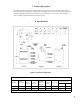
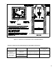
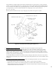
I Product Description The CHG is an aluminum gas fired condensing boiler designed for use in forced hot water heating systems requiring supply water temperatures of 180°F or less. This boiler may be vented vertically or horizontally with combustion air supplied from outdoors. This boiler is not designed for use in gravity hot water systems or systems containing significant amounts of dissolved oxygen. II Specifications Figure 2.1: General Configuration Table 2.2: Specifications MODEL* NO.
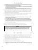
III Before Installing 1) Safe, reliable operation of this boiler depends upon installation by a professional heating contractor in strict accordance with this manual and the authority having jurisdiction. • In the absence of an authority having jurisdiction, installation must be in accordance with this manual and the National Fuel Gas Code, ANSI Z223.1.
Figure 4.1: Clearances To Combustible Or Non-combustible Material Table 4.
WARNING OUTDOOR COMBUSTION AIR MUST BE PIPED TO THE AIR INTAKE. NEVER PIPE COMBUSTION AIR FROM AREAS CONTAINING CONTAMINATES SUCH AS SWIMMING POOLS AND LAUNDRY ROOM EXHAUST VENTS. CONTAMINATED COMBUSTION AIR WILL DAMAGE THE BOILER AND MAY CAUSE PROPERTY DAMAGE, PERSONAL INJURY OR LOSS OF LIFE AND WILL VOID THE MANUFACTURER’S WARRANTY. V Air for Ventilation Air for combustion must always be obtained directly from outdoors, however sufficient air for ventilation must still be provided in the boiler room.
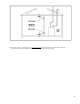
Figure 5.1: Boiler Installed In A Confined Space, Ventilation Air From Inside Step 2b: If the boiler is to be placed in an unconfined space the natural infiltration into the boiler room will provide adequate air for ventilation without additional openings into boiler room.
VI Venting WARNING Failure to vent this boiler in accordance with these instructions could result in unreliable boiler operation, severe damage to the boiler or property, or unsafe operation: • • • • • • Do not attempt to vent this boiler with galvanized, PVC, or any other vent system not listed in Table 4. Do not attempt to mix components from different approved vent systems. Do not obtain combustion air from within the building. Do not install a barometric damper or drafthood on this boiler.
The Vent Option #1 column in Table 6.2a describes a horizontal direct vent system using 3” vent pipe. From this column, we see that a CHG150 may have a vent length of up to 55ft. The first 90 elbow and the termination elbow are not considered. From Table 6.6, the equivalent length of the 3” 45 elbow is 4ft and the equivalent length of the 3” 90 degree elbow is 5.5ft. The maximum allowable run of straight pipe on this system is therefore: 55ft – 4 ft – 5.
• The bottom of the vent and air intake terminals must be at least 12” above the normal snow line. In no case should they be less than 12” above grade level. • The bottom of the vent terminal must be at least 7 feet above a public walkway. • Do not install the vent terminal directly over windows or doors. • The bottom of the vent terminal must be at least 3 feet above any forced air inlet located within 10 feet.
Table 6.2b: Summary of Vertical Venting Options VENT OPTION # CLASSIFICATION USED IN THIS MANUAL 6 VERTICAL DIRECT VENT VERTICAL DIRECT VENT 6.4 6.4 VENT PIPE STRUCTURE PENETRATION ROOF ROOF AIR INTAKE PIPE STRUCTURE PENETRATION ROOF ROOF VENT PIPE SIZE 3” 4” AIR INTAKE PIPE SIZE 4” 4” CHG150 49.5 FT N.R. CHG225 N.R. 47 FT CHG150 52 FT N.R. CHG225 N.R.
Figure 6.3a: Location of Vent Terminal Relative to Windows, Doors, Grade Figure 6.3b: Location of Vent Terminal Relative to Meters and Forced Air Inlets Figure 6.
• Air intake terminal must not terminate in areas that might contain combustion air contaminates, such as near swimming pools. See Section IV for more information on possible contaminates. 6) Permitted Terminals for Vertical Venting (Vent Options 6, 7) - A rodent screen is installed in the end of the vent pipe. Vent manufacturer part numbers for these screens are shown in Table 4. The air inlet terminal consists of a 180 degree elbow (or two 90 degree elbows) with a rodent screen as shown in Figure 6.4.
Table 6.5: Burnham Vent/Air Intake System Components Equivalent Feet of Pipe Vent System Component Part Number 3” Dia. Pipe x 1 Ft. 8116296U 4” Dia. Pipe x 1 Ft. 100176-01 3” Dia. Pipe x 3 Ft. 8116298U 4” Dia. Pipe x 3 Ft. 100177-01 3” Dia. Pipe x 5 Ft. 8116300U 4” Dia. Pipe x 5 Ft. 100178-01 3” Dia. Pipe x Adjustable 8116319U 4” Dia. Pipe x Adjustable 100179-01 **Equal to Installed Length (1.06 to 1.64) 3” Dia. 90° Elbow 8116294U 5.5 VENT FITTING 4” Dia. 90° Elbow 100180-01 8.
B. Removing an Existing Boiler From a Common Chimney Read this only if the CHG boiler is replacing an existing boiler that is being removed from a common chimney. This section does not apply to the installation of a CHG boiler. In some cases, when an existing boiler is removed from a common chimney, the common venting system may be too large for the remaining appliances.
2) This appliance requires a Special Gas Vent. The product is designed to use Burnham supplied AL 29-4C® Stainless Steel vent system components when utilizing the supplied vent adaptor. The following manufacturers offer similar AL 29-4C® components and are approved for use with this product. The use of these alternate manufacturer’s venting systems can be utilized by connecting directly to the installed vent pipe (supplied adaptor is not required). See Table 6.
Figure 6.7a: Star-34 Connection to Vent Collar Figure 6.7b: Star-34 Connections l) Cut the excess joiner band so that it lays flat in the beaded channel (Fig 6.7b). m) Fill the inlet of the beaded channel with silicone. Smooth the silicone over the channel inlet as well as the silicone between the female end and the stop bead of the male end (Fig 6.7b). n) Repeat Steps (h) – (m) for the remaining Star-34 components.
i) Align the second piece of pipe with the first and push them together as far as they will go, but not less j) k) l) n) than 1-3/4”. Tighten gear clamp to a minimum torque of 40 in-lbs and a maximum of 50 in-lbs. Repeat Steps (h) – (j) for the remaining Z-Vent III components. In horizontal vent systems, a locking band or gear clamp must be used at either side of the wall penetration to prevent shifting of the vent system in and out of the wall. This applies to both combustible and noncombustible walls.
Figure 6.9: SAF-T Vent Ezseal Connection to Vent Collar 7) Assembly of Protech FasNSeal a) FasNSeal General Notes: • • Do not cut 4” FasNSeal pipe. Consult FasNSeal instructions for method of cutting other 3” pipe. Orient FasNSeal vent components so that the arrows on the piping labels are in the direction of flue gas flow. • Support horizontal piping sections at intervals of 6 feet or less. • Vertical venting systems must be supported by at least one FasNSeal support.
Figure 6.10: FasNSeal Connection to Vent Collar VII Condensate Drain Line 1) All condensate which forms in the boiler or vent system collects in the sump under the heat exchanger and leaves the boiler through the condensate trap. This trap allows condensate to drain from the sump while retaining flue gases in the boiler. A length of drain hose is supplied with the boiler and is connected to the trap as shown in Figure 6.11.
Figure 6.11: Condensate Piping Arrangement WARNING BOILER CONDENSATE IS CORROSIVE. ROUTE CONDENSATE DRAIN LINE IN A MANNER SUCH THAT ANY CONDENSATE LEAKAGE WILL NOT CAUSE PROPERTY DAMAGE. SOME JURISDICTIONS MAY REQUIRE THAT CONDENSATE BE NEUTRALIZED PRIOR TO DISPOSAL.
VIII Gas Piping Gas piping to the boiler must be sized to deliver adequate gas for the boiler to fire at the nameplate input at an inlet pressure between the minimum and maximum values shown on the rating plate. For more information on gas line sizing, consult the utility or the National Fuel Gas Code. Figure 7.1 shows typical gas piping connection to the CHG boiler. A sediment trap must be installed upstream of all gas controls.
IX System Piping A. General System Piping Precautions CAUTION THE HEAT EXCHANGER USED IN THE CHG IS MADE FROM A SPECIAL ALUMINUM ALLOY. FAILURE TO TAKE THE FOLLOWING PRECAUTIONS COULD RESULT IN SEVERE BOILER DAMAGE AND WILL VOID THE MANUFACTURER’S WARRANTY. • INSTALL BOILER SO THAT THE GAS IGNITION SYSTEM COMPONENTS ARE PROTECTED FROM WATER (DRIPPING, SPRAYING, RAIN, ETC) DURING APPLIANCE OPERATION AND SERVICE (CIRCULATOR REPLACEMENT, ETC).
Method 1: Primary/Secondary Piping - Boiler in Secondary Loop This method can be used in heat-only applications as shown in Figure 8.2 or with an indirect water heater as shown in Figure 8.3. This method relies on primary/secondary pumping to ensure that the required flow is always maintained through the boiler. In this system, the flow rate through the boiler is completely independent of the flow rate through the heating system.
Figure 8.2: Piping Method #1 - Heat Only Figure 8.
Figure 8.4a: Piping Method #1 - Secondary Loop Piping (Shaded) Figure 8.
Table 8.5: Pipe and Circulator Sizing for Boiler Loop (a) (b) PIPE SIZE FLOW (in NPT) (GPM) CHG150 1 1/4 8.0 Taco 007 148 CHG150 1 1/4 8.0 Taco 0010 224 CHG225 1 1/4 12.0 Taco007 138 CHG225 1 1/4 12.0 Taco 0010 208 BOILER MODEL (c) (d) CIRCULATOR MODEL BOILER LOOP MAX EQUIVALENT LENGTH (ft) NOTE: For piping method #1, “boiler loop” is heating system secondary loop For piping method #2, “boiler loop” is heating system primary loop Table 8.
Method 2: Primary/Secondary Piping - Boiler in Primary Loop This method can be used in heat-only applications as shown in Figure 8.8 or with an indirect water heater as shown in Figure 8.9. Like Method 1, this method relies on primary/secondary pumping to ensure that the required flow is always maintained through the boiler. In this system, the flow rate through the boiler is completely independent of the flow rate through the heating zones.
Figure 8.8: Piping Method #2 - Heat Only Figure 8.
Figure 8.10a: Piping Method #2 - Secondary Loop Piping (Bolded) Figure 8.
Figure 8.10c: Piping Method #2 - Indirect Water Heater Loop Piping (Bolded) Figure 8.
Head Loss (Feet w.c.) 6.00 5.00 4.00 3.00 CHG150 2.00 CHG225 1.00 0.00 0 5 Figure 8.12: Boiler Head Loss 10 15 20 25 Flow (GPM) C: Standard Piping Installation Requirements Observe the following guidelines when making the actual installation of the boiler piping: 1) The relief valve is packaged loose with the boiler and must be installed in the location shown in Figure 1. The relief valve is set to open at 30 psi.
3) The return piping may be connected into the boiler through the back or sides of the boiler by rotating the drain elbow and routing the return piping through the appropriate knockout. 4) Circulator (Required) - Usually at least two circulators will be required to properly install a CHG Series boiler. See previous section (System Design) for information on sizing the circulators.
Figure 8.13: Isolation of the Boiler From Oxygenated Water with A Plate Heat Exchanger Figure 8.
X Wiring WARNING All wiring and grounding must be done in accordance with the authority having jurisdiction or, in the absence of such requirements, with the National Electrical Code (ANSI/NFPA 70). 1) Line Voltage (120 VAC) Connections (Fig 9.
Figure 9.
Figure 9.
Figure 9.
XI Start-up and Checkout NOTE SAFE LIGHTING AND OTHER PERFORMANCE CRITERIA WERE MET WITH THE GAS TRAIN ASSEMBLY PROVIDED ON THE BOILER WHEN THE BOILER UNDERWENT THE TEST SPECIFIED IN Z21.13. Use the following procedure for initial start-up of the boiler: 1) If not already done, flush the system to remove sediment, flux, and traces of boiler additives. This should be done with the boiler isolated from the system.
CHG Series Lighting and Operating Instructions 40
7) Start the boiler using the lighting instructions on page 40. After the boiler is powered up, it should go through the following sequence. Sequence Display Meaning 1 U.125 or Blank Checking internal software (power-up only) 2 0.SWT Boiler in standby. SWT = Supply Water Temp. No call for heat. (After call for heat from heating thermostat) 3 A.SWT Self-Check on Start-up 4 5.SWT Blower and circulator on. Checking for adequate air flow. 5 1.
Figure 10.2: Gas Valve Detail 11) Perform a combustion test. On horizontally vented units, the sample probe may be inserted into the terminal. If this is not possible, and if no sample tap is present in the vent system, remove the flue temperature sensor and insert the analyzer probe in the sensor opening. On the CHG150 and CHG225 the flue temperature probe is located behind the lower vestibule door. For the boiler to operate, this sensor will need to be temporarily connected outside of the boiler.
12) Test any external limits or other controls in accordance with the manufacturer’s instructions. 13) Verify that the boiler starts and stops in response to calls for heat from the heating thermostat and indirect water heater thermostat. Make sure that the appropriate circulators also start and stop in response to the thermostats. 14) As shipped, the heating and indirect water heater set point supply temperatures are both set to 180°F.
XII Operation 1) The CHG boiler uses a microprocessor based control, known as a “MCBA”, to manage all boiler functions including flame supervision and modulation. Two set point or “target” boiler supply temperatures are stored in the MCBA’s memory; one for space heating and one for domestic water production. If an outdoor temperature sensor is connected to the boiler, the space heating supply set point will automatically adjust downwards as the outdoor temperature increases.
In standby mode, it is possible to view both the heating supply set point temperature and the “domestic hot water reference set point”. The “domestic hot water reference set point” plus 45°F equals the boiler supply set point when it is responding to a call from the indirect water zone. It is not the actual domestic hot water set point. The CHG is designed for use with a storage type indirect water heater such as the Burnham Alliance™.
Figure 11.
3) Two basic types of errors codes are shown on the display: • Soft Lockout Codes – When a soft lockout occurs, the boiler will shut down and the display will alternate between the number “9” and the letter “b” followed by a two digit service code. A list of these codes, and their meanings, is shown in Table 13.3. The boiler will automatically restart once the condition that caused the lockout is corrected.
Figure 11.4: Outdoor Reset Curve 7) The sequence of operation for a CHG series boiler on a call for heat from a thermostat is as described below: a) When power is first turned on, 120V is provided to the MCBA, the combustion fan and the LWCO trans- former. A separate 50VA transformer, connected directly to the MCBA, powers all other low voltage circuits. b) For the first few seconds after power-up the control module goes through a self check.
XIII Service and Maintenance IMPORTANT WARRANTY DOES NOT COVER BOILER DAMAGE OR MALFUNCTION IF THE FOLLOWING STEPS ARE NOT PERFORMED AT THE INTERVALS SPECIFIED. 1) Continuously: a) Keep the area around the boiler free from combustible materials, gasoline and other flammable vapors and liquids. b) Keep the area around the combustion air inlet terminal free from contaminates . c) Keep the boiler room ventilation openings open and unobstructed.
d) Remove the ignition electrode and inspect it for oxides. Clean the oxides off the electrode with sandpaper. Inspect the ceramic insulator for cracks and replace the ignitor assembly as necessary. e) Remove any accumulated debris from the air inlet screen. f) Remove the attenuator hose and clean as necessary. (Note: The nylon cable tie used to hold the attenuator hose in place is releasable.) g) Remove the combustion fan/gas valve assembly and inspect the fan and fan blade for lint and dust.
XIV Troubleshooting WARNING Turn off power to boiler before replacing fuses or working on wiring. A. Troubleshooting problems where no error code is displayed: Table 13.1: No Error Code Displayed CONDITION POSSIBLE CAUSES Display Blank, Fan off, LWCO lights off • No 120VAC Power at boiler. Check breaker and wiring between breaker panel and boiler Display Panel Blank, Fan running • Loose 120VAC connection wiring between boiler J-Box and MCBA • Blown “F1” fuse in MCBA (see Figure 13.2 for location).
B. Trouble shooting problems where a soft lockout code is displayed. When a soft lockout occurs, the boiler will shut down and the display will alternate between the number “9” and the letter “b” followed by a two digit service code. The boiler will automatically restart once the condition that caused the lockout is corrected. Table 13.3: Soft Lockout Codes Displayed CODE POSSIBLE CAUSES Pressure switch circuit open • Blockage in intake or vent system.
C. Trouble shooting problems where a hard lockout code is displayed. When a hard lockout occurs, the boiler will shut down and the display will flash the letter “E” followed by a two digit service code. Once the condition that caused the lockout is corrected, the boiler will need to be manually reset using the RESET button on the display. Table 13.4: Hard Lockout Codes Displayed CODE CONDITION POSSIBLE CAUSES E 00 A flame signal was present when there should be no flame.
SERVICE RECORD DATE 54 SERVICE PERFORMED
XV Parts All CHG Series Repair Parts may be obtained through your local Burnham Wholesale distributor. Should you require assistance in locating a Burnham distributor in your area, or have questions regarding the availability of Burnham products or repair parts, please contact Burnham Customer Service at (717) 481-8400 or Fax (717) 481-8408.
CHG REPLACEMENT PARTS LIST CHG150 KEY 56 DESCRIPTION CHG225 BURNHAM PART # QUANTITY BURNHAM PART # QUANTITY 3 #8-32 x 1/4” H.W.H. Screw 100401-01 2 100401-01 2 4 Front Door Panel 100402-01 1 100402-02 1 5 #6-32 Hex Nylon Insert LockNut 100403-01 4 100403-01 4 6 Control Chassis Assembly 100404-01 1 100404-01 1 7 .125” ID x .250”OD Silicone Tubing 100405-01 1.25’ 100405-01 1.25’ 8 .125” ID x .250”OD Silicone Tubing 100406-01 5.0’ 100406-01 5.
CHG REPLACEMENT PARTS LIST CHG150 KEY DESCRIPTION BURNHAM PART # CHG225 QUANTITY BURNHAM PART # QUANTITY 47 Nylon Glide Foot 1”Dia x 3/4” Long 100444-01 4 100444-01 4 48 Combination Base / Rear Panel 100445-01 1 100445-02 1 49 Vesibule Top Panel Assembly 100446-01 1 100446-02 1 50 Vent Seal Gasket 100447-01 1 100447-02 1 51 Vent Adapter Assembly 100448-01 1 100448-02 1 52 8-32 Hex Nylon Insert Locknut 100449-01 4 100449-01 4 53 Display Board 100450-01 1 100450-
CHG REPLACEMENT PARTS LIST CHG150 KEY 62 DESCRIPTION CHG225 BURNHAM BURNHAM QUANTITY QUANTITY PART # PART # 89 #6-32 x 13mm Hex x 92mm, Long Standoff 100488-01 2 100488-01 2 90 M6 x 1.0 x 75mm, Hex Head Screw 100489-01 16 100489-01 16 91 Manifold Seal Ring, EPDM 100490-01 8 100490-01 8 92 M6 x 1.0 x 30mm, SS Hex Socket Set Screw 100491-01 6 100491-01 6 93 M6 x 1.0, Lock Washer 100492-01 6 100492-01 6 94 M4 x 0.7 x 12mm, Phillips Pan Head Mach.
CHG REPLACEMENT PARTS LIST CHG150 KEY 64 DESCRIPTION BURNHAM PART # CHG225 QUANTITY BURNHAM PART # QUANTITY Not Shown 11-1/2” Releasable Nylon Cable Wire Tie 100533-01 1 100533-01 1 Not Shown 6” Nylon Wire Tie 100534-01 10 100534-01 11 Not Shown 1-5/8” Hole Plug 100535-01 1 100535-01 1 Not Shown 5mm x 20mm Fast Acting, Ceramic Tube, 5 Amp Fuse 100536-01 1 100536-01 1 Not Shown 5mm x 20mm Time Delay, Glass Tube, 4 Amp Fuse 100537-01 1 100537-01 1 Not Shown 1/2” NPT x 3-
Appendix A: Special Requirements For Side-Wall Vented Appliances In The Commonwealth of Massachusetts IMPORTANT The Commonwealth of Massachusetts requires compliance with regulation 248 CMR 4.00 and 5.00 for installation of side-wall vented gas appliances as follows: 1.
SERVICE RECORD DATE SERVICE PERFORMED 69
SERVICE RECORD DATE 70 SERVICE PERFORMED
SERVICE RECORD DATE SERVICE PERFORMED 71
9EARS IN 3ERVICE 3ERVICE #HARGE AS OF 2ETAIL 0RICE .