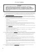
IN S TAL L AT ION , OP E R AT IN G AN D S E R V IC E IN S T R U C T ION S F OR F R E E D OM ™ C ON D E N S IN G H IGH E F F IC IE N C Y D IR E C T V E N T GA S - F I R E D H OT WAT E R BOI L E R Warning: Improper installation, adjustment, alteration, service or maintenance can cause property damage, injury, or loss of life. For assistance or additional information, consult a qualified installer, service agency or the gas supplier. This boiler requires a special venting system.
Table of Contents I. Product Description............................................................................. 3 II. Specifications...................................................................................... 3 III. Before Installing................................................................................... 4 IV. Locating The Boiler.............................................................................. 4 V. Mounting The Boiler...................................................
I Product Description The FCM070, FCM090 and FCM120 are aluminum gas fired condensing boilers designed for use in forced hot water heating systems requiring supply water temperatures of 180°F or less. These boilers are designed for installation on a wall, however they may be floor mounted using an optional pedestal kit available from U.S. Boiler Company, Inc. This boiler may be vented vertically or horizontally with combustion air supplied from outdoors.
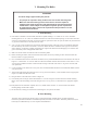
III Before Installing 1) Safe, reliable operation of this boiler depends upon installation by a professional heating contractor in strict accordance with this manual and the authority having jurisdiction. • In the absence of an authority having jurisdiction, installation must be in accordance with this manual and the National Fuel Gas Code, ANSI Z223.1.
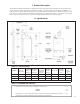
6) The combustion air piping must terminate where outdoor air is available for combustion and away from areas that will contaminate combustion air. Avoid areas near chemical products containing chlorine, chloride based salts, chloro/ fluorocarbons, paint removers, cleaning solvents and detergents. Figure 4.
Table 4.
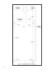
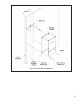
V Mounting The Boiler CauTiOn This boiler weighs approximately 110 pounds: • Two people are required to safely lift this boiler onto the wall mounting hook. • Make sure that wall mounting hook is anchored to a structure capable of supporting the weight of the boiler and attached piping when filled with water. Jurisdictions in areas subject to earthquakes may have special requirements for supporting this boiler. These local requirements take precedence over the requirements shown below. A.
Figure .
Figure 5.
VI Air for Ventilation WARNING OUTDOOR COMBUSTION AIR MUST BE PIPED TO THE AIR INTAKE. NEVER PIPE COMBUSTION AIR FROM AREAS CONTAINING CONTAMINATES SUCH AS SWIMMING POOLS AND LAUNDRY ROOM EXHAUST VENTS. CONTAMINATED COMBUSTION AIR WILL DAMAGE THE BOILER AND MAY CAUSE PROPERTY DAMAGE, PERSONAL INJURY OR LOSS OF LIFE. Air for combustion must always be obtained directly from outdoors, however sufficient air for ventilation must still be provided in the boiler room.
Figure 6.
VII Venting WARNING FAILURE TO VENT THIS BOILER IN ACCORDANCE WITH THESE INSTRUCTIONS COULD CAUSE FLUE GAS TO ENTER THE BUILDING RESULTING IN SEVERE PROPERTY DAMAGE, PERSONAL INJURY, OR DEATH: * Do not attempt to vent this boiler with galvanized, PVC, or any other vent system not listed in Tables 7.4a or 7.4b. * Do not attempt to mix components from different approved vent systems. * Do not obtain combustion air from within the building. * Do not install a barometric damper or drafthood on this boiler.
2) Maximum Vent and Air Intake Lengths - The maximum length of the vent air intake piping depends upon the vent option selected and the boiler size. See Table 7.1 or 7.9 for the maximum vent length. In horizontal vent systems, the lengths shown in Table 7.1 are in addition to the first standard elbow on top of the boiler. For vertical vent systems, the maximum vertical vent lengths shown in Table 7.9 are in addition to two elbows.
Horizontal Terminal Clearance Requirements (Continued): • Vent terminal must be at least 6 feet from an inside corner. • Under certain conditions, water in the flue gas may condense, and possibly freeze, on objects around the vent terminal including on the structure itself. If these objects are subject to damage by flue gas condensate, they should be moved or protected. • If possible, install the vent and air intake terminals on a wall away from the prevailing wind.
Figure 7.2: Horizontal Concentric Venting (Vent Options 1, 3) Figure 7.
TABLE 7.4a: U.S. Boiler CONCENTRIC 60/100 VENT COMPONENTS (VENT OPTION 1) PART NO.
6) Permitted Terminals for Vertical Venting • Vent Option 5 - A straight termination is installed in the end of the vent pipe. Vent manufacturer part numbers for these screens are shown in Table 7.5. The air inlet terminal consists of a 180 degree elbow (or two 90 degree elbows) with a rodent screen as shown in Figure 7.10 • Vent Option 6 - Use U.S. Boiler part 101495-01 with the appropriate flashing (see Table 7.4b).
Figure 7.6a: Location of Vent Terminal Relative to Windows, Doors, Grade Figure 7.6b: Location of Vent Terminal Relative to Meters and Forced Air Inlets Figure 7.
9) Pitch of Horizontal Piping - Pitch all horizontal piping so that any condensate which forms in the piping will run towards the boiler: • • Pitch U.S. Boiler horizontal concentric venting 5/8” per foot Pitch Stainless steel venting 1/4” per foot. 10) Supporting Pipe - Vertical and horizontal sections of pipe must be properly supported: • Support U.S. Boiler concentric venting near the female end of each straight section of pipe.
TABLE 7.8: VENT/ AIR INTAKE FITTING EQUIVALENT LENGTH VENT FITTING EQUIVALENT LENGTH (ft) 60/100mm 90° CONCENTRIC ELBOW 4.5 60/100mm 45° CONCENTRIC ELBOW 4.0 80/125mm 90° CONCENTRIC ELBOW 8.5 80/125mm 90° SWEEP CONCENTRIC ELBOW 5.5 80/125mm 45° CONCENTRIC ELBOW 3.0 80/125mm 90° CONCENTRIC SUPPORT ELBOW 8.5 3” SINGLE WALL 90° ELBOW 5.5 3” SINGLE WALL 45° ELBOW 4.0 TABLE 7.
Figure 7.10: Vertical Twin Pipe Vent System (Vent Option 5) Figure 7.
B. Removing an Existing Boiler From a Common Chimney Read this only if the FCM boiler is replacing an existing boiler that is being removed from a common chimney. This section does not apply to the installation of a FCM boiler. In some cases, when an existing boiler is removed from a common chimney, the common venting system may be too large for the remaining appliances.
C. Assembly of U.S. Boiler 60/100mm Concentric Venting (IMPORTANT - Skip to Section D for 80/125mm Concentric Vent Assembly) WARNING Failure to follow the instructions could result in flue gas leakage into the combustion air or indoor air, resulting in unsafe or unreliable operation • Do not lubricate concentric gaskets with anything other than water. • Do not attempt to cut any piping except as permitted in this section.
Figure 7.20: Installation of Reducing Elbow on Concentric Boiler Collar Figure 7.
6) Use locking bands provided to join adjacent sections of non-cuttable pipe as well as fittings. The male end of the terminal section and other cuttable sections must be held to the female end of the adjoining pipe with at least three #10 x 1/2” sheet metal screws. Drill a 1/8" hole through both outer pipes to start this screw. Use a drill stop or other means to ensure that the drill bit does penetrate more than 3/8” into the outer pipe. Do not use a sheet metal screw longer than 1/2”.
Figure 7.24: Preparing 60/100mm Terminal Section for Installation in the Wall Figure 7.
D. Assembly of U.S. Boiler 80/125mm Concentric Venting (IMPORTANT - See Section C for 60/100mm Concentric Vent Assembly) WARNING Failure to follow the instructions could result in flue gas leakage into the combustion air or indoor air, resulting in unsafe or unreliable operation • Do not lubricate concentric gaskets with anything other than water. • Do not attempt to cut any piping except as permitted in this section. When cutting these sections, make sure all cuts are square and allow for proper insertion.
To cut the straight sections listed above refer to Figure 7.31 and the following instructions: a) Determine the required length of the outer pipe. When doing this allow an additional 1" of length for insertion into the female end of the adjoining pipe. Mark the cut line on the outer pipe. b) Remove the plastic inner pipe by pulling it out from the female end. c) Cut the OUTER PIPE ONLY at the point marked in Step (a) using aviation shears, a hacksaw, or an abrasive wheel cutter.
3) Joining Pipe a) Start assembly of the vent system at the boiler. Lubricate the brown gasket in the boiler vent collar with a few drops of water. b) Push the male end of the first fitting into the boiler collar until it bottoms out. The male end of cuttable sections should go 1” into the collar until the insertion mark (made in Step 2d above) is covered. On other fittings, the bead on the male pipe will be bottom out on the collar (Figure 7.32b).
4) 80/125mm Horizontal Terminal Installation a) Cut a 5-1/2” diameter hole through the exterior wall at the planned location of the horizontal terminal. b) Measure distance “L” from the outside surface of the exterior wall to the end of the last fitting as shown in Figure 7.33a. c) Add 1-1/4” to distance “L”. Carefully mark this length on the pipe as shown in Figure 7.33b. d) Remove the plastic inner pipe from the terminal, by gently pulling on it from the male end. Set aside.
Figure 7.33c: Cutting Inner Pipe of 80/125mm Horizontal Terminal Figure 7.
5) Snorkel Terminal Installation - The Snorkel Kit (P/N 101544-01) consists of the following (Also see Figure 7.34): Key No. Part No.
d) Complete the vent system inside the structure. The support elbow sits on the M10 x 35 screw as shown in Figure 7.34. Cut the Wall Penetration Section to the length required to connect the interior vent system to the Support Elbow following the instructions on Page 27. e) Remove the Support Elbow from the Lower Support Bracket and attach it to the Wall Penetration Section. Slip this assembly through the Lower Support Bracket. Connect to the interior vent system.
Figure 7.35b: Cutting Vertical Terminal Figure 7.
7) Chimney Chase Installation - A vertical 80/125mm vent system can be installed in an unused masonry chimney. This installation is similar to other vertical installations with the following exceptions (Also see Figure 7.36): a) The chimney chase elbow kit (P/N 101492-01) is used at the base of the chimney. This kit consists of a support elbow and a mounting bracket. Slip the elbow over the M10 x 35 screw in the support bracket.
E. Assembly of Stainless Steel Venting CAUTION Vent systems made by Heat Fab, Protech, and Z-Flex rely on gaskets for proper sealing. When these vent systems are used, take the following precautions: • Make sure that gasket is in position and undamaged in the female end of the pipe. • Make sure that both the male and female pipes are free of damage prior to assembly. • Only cut vent pipe as permitted by the vent manufacturer in accordance with their instructions.
3) Assembly of Metal-Fab Corr/Guard Vent System: a) Corr/Guard General Notes: • Do not cut Corr/Guard vent components. • Refer to Corr/Guard installation instructions for proper methods of support. • Orient Corr/Guard components so that the males ends of all fittings point in the direction of the boiler. b) Start assembly of the vent system at the boiler. Remove the hose clamp shipped on the FCM vent collar. Bend the three hose clamp tabs on this collar outward slightly.
4) Assembly of Z-Flex Z-Vent III: a) General Notes: • Non-expanded ends of SVE Series III piping sections may be cut using aviation snips or a 24 thread per inch hacksaw. File or sand the cut end smooth before assembling. Expanded ends may be cut to adapt the SVE Series III to the vent collar. See the following instructions. • Support horizontal piping sections at intervals of 48” or less. • Vertical venting systems must be supported by at least one Z-Flex fire stop.
5) Assembly of Heat Fab Saf-T Vent EZ Seal: a) Saf-T Vent General Notes: • • • • • These instructions cover the installation of Saf-T Vent EZ Seal. Saf-T Vent EZ Seal piping has integral gaskets installed in the female ends of the pipe which seal the joints. In general, Saf-T Vent pipe sections may not be cut. Exceptions to this are the Saf-T Vent slip connector and connections to the boiler vent collar. In these cases, use a sharp pair of aviation snips, an abrasive cut-off, or a plasma cutter.
6) Assembly of Protech FasNSeal a) FasNSeal General Notes: • Do not cut 4” FasNSeal pipe. Consult FasNSeal instructions for method of cutting other 3” pipe. • • • Orient FasNSeal vent components so that the arrows on the piping labels are in the direction of flue gas flow. Support horizontal piping sections at intervals of 6 feet or less. Vertical venting systems must be supported by at least one FasNSeal support. An additional vertical support is required after any offset.
8) Installation of Vertical Exhaust Terminal - Use the terminal supplied by the vent system manufacturer shown in Table 7.5. Attach to the vent system, following the assembly instructions in this manual for the stainless vent system being used. 9) Assembly of the Air Intake System and Air Intake Terminals: a) Assemble the air intake system using either galvanized or PVC pipe. b) If PVC piping is used, use PVC cement to assemble the PVC intake system components.
FIGURE 7.
VIII Gas Piping Gas piping to the boiler must be sized to deliver adequate gas for the boiler to fire at the nameplate input at an inlet pressure between the minimum and maximum values shown on the rating plate. For more information on gas line sizing, consult the utility or the National Fuel Gas Code. Figure 8.1 shows typical gas piping connection to the FCM boiler. A sediment trap must be installed upstream of all gas controls.
IX System Piping A. General System Piping Precautions WARNING INSTALL BOILER SO THAT THE GAS IGNITION SYSTEM COMPONENTS ARE PROTECTED FROM WATER (DRIPPING, SPRAYING, RAIN, ETC) DURING APPLIANCE OPERATION AND SERVICE (CIRCULATOR REPLACEMENT, ETC). CAUTION THE HEAT EXCHANGER USED IN THE FCM IS MADE FROM A SPECIAL ALUMINUM ALLOY. FAILURE TO TAKE THE FOLLOWING PRECAUTIONS COULD RESULT IN SEVERE BOILER DAMAGE.
Method 1: Primary/Secondary Piping This method can be used in heat-only applications as shown in Figure 9.2 or with an indirect water heater as shown in Figure 9.3. This method relies on primary/secondary pumping to ensure that the required flow is always maintained through the boiler. In this system, the flow rate through the boiler is completely independent of the flow rate through the heating system. Use the following guidelines to ensure that the boiler will have the required flow shown in Table 9.
Example (contd.) Total fittings in Indirect Water Heater Loop: 5 90 Elbows 2 Turns in Tees 1 Swing Check 2 Isolation Valves Calculate total equivalent length from Table 9.7: 20 Straight Pipe + 5 Elbows x 2.75 + 2 Turns in Tees x 5.5 + 1 Swing Check x 7 + 2 valves x 0.6 = 52.95 Equivalent Feet Straight Pipe. From Table 9.6, we see that smallest circulator which will pump at 8 GPM through a FCM120 with 52.95 equivalent feet and an indirect water heater pressure drop of 3 ft is a Taco 0014. Figure 9.
Figure 9.3: Piping Method #1 - Heat + Indirect Water Heater Figure 9.
Figure 9.4b: Piping Method #1 - Indirect Water Heater Loop Piping (Shaded) TABLE 9.5: PIPE AND CIRCULATOR SIZING FOR BOILER LOOP (a) (b) (c) (d) (e) PIPE SIZE (in NPT) FLOW (GPM) TEMP RISE (F) CIRCULATOR MODEL BOILER LOOP MAX EQUIVALENT LENGTH (ft) FCM070 1 6.0 22 Taco 007 55 FCM070 1 6.0 22 Taco 008 145 FCM090 1 8.0 21 Taco 0014 90 FCM090 1 8.0 21 Taco 0013 (Note #1) 230 FCM120 1 8.0 29 Taco 0014 111 FCM120 1 9.0 25 Taco 0014 61 FCM120 1 12.
TABLE 9.6: PIPE AND CIRCULATOR SIZING FOR INDIRECT WATER HEATER LOOP BOILER MODEL FCM070 FCM090 FCM090 FCM120 FCM120 FCM120 (a) (b) (c) PIPE SIZE FLOW MAX. I.W.H. PRESSURE DROP (in NPT) (GPM) (ft HEAD) 1 1 1 1 1 1 6.0 8.0 8.0 8.0 8.0 8.0 (d) (e) (f) ALLIANCE™ INDIRECT WATER HEATERS CIRCULATOR MODEL I.W.H. LOOP MAX EQUIVALENT LENGTH (ft) 1.7 AL27SL (*) AL35SL (*) AL70SL (*) AL119SL (*) Taco 008 102 3.
Method 2: Direct Connection to Heating System (Generally NOT Recommended) The FCM can be connected directly to the heating system as is done with conventional boilers (Figure 9.8). If this is done, the flow rate through the boiler will equal the flow rate through the system. The flow rate through the system must therefore always remain within the limits shown in Table 9.1.
Figure 9.9: Boiler Head Loss C: Standard Piping Installation Requirements Observe the following guidelines when making the actual installation of the boiler piping: 1) The relief valve is packaged loose with the boiler and must be installed in the location shown in Figure 2.1. The relief valve is set to open at 30 psi. If the valve is replaced, the replacement must have a relief capacity in excess of the DOE heating capacity for the boiler.
2) Circulator (Required) - Usually at least two circulators will be required to properly install a FCM Series boiler. See the previous section for information on sizing the circulators. 3) Expansion Tank (Required) - If this boiler is replacing an existing boiler with no other changes in the system, the old expansion tank can generally be reused. If the expansion tank must be replaced, consult the expansion tank manufacturer’s literature for proper sizing.
Figure 9.10: Isolation of the Boiler From Oxygenated Water with A Plate Heat Exchanger Figure 9.
X Wiring WARNING All wiring and grounding must be done in accordance with the authority having jurisdiction or, in the absence of such requirements, with the National Electrical Code (ANSI/NFPA 70). 1) Line Voltage (120 VAC) Connections (Figure 10.
Figure 10.
Figure 10.
Figure 10.
XI Start-up and Checkout NOTE SAFE LIGHTING AND OTHER PERFORMANCE CRITERIA WERE MET WITH THE GAS TRAIN ASSEMBLY PROVIDED ON THE BOILER WHEN THE BOILER UNDERWENT THE TEST SPECIFIED IN Z21.13. Use the following procedure for initial start-up of the boiler: 1) If not already done, flush the system to remove sediment, flux, and traces of boiler additives. This should be done with the boiler isolated from the system.
WATER QUALITY AND BOILER WATER ADDITIVES IMPORTANT NOTE This boiler is equipped with an aluminum heat exchanger that can be seriously damaged by failure to follow the following guidelines: 1) Flush the system before connecting the boiler - In a replacement installation, flushing the system will remove sediment, solder flux, and traces of old boiler additives. Even if the system is new, do not omit this step - new systems will contain solder flux and may even contain sediment.
FCM Series Lighting and Operating Instructions 60
7) Start the boiler using the lighting instructions on page 49. After the boiler is powered up, it should go through the following sequence. Sequence Display Meaning 1 U.125 or Blank Checking internal software (power-up only) 2 0.SWT Boiler in standby. SWT = Supply Water Temp. No call for heat. (After call for heat from heating thermostat) 3 A.SWT Self-Check on Start-up 4 5.SWT Blower and circulator on. Checking for adequate air flow. 5 1.SWT Prepurge 6 2.
Figure 11.2: Gas Valve Detail 11) Perform a combustion test. Boilers equipped with a concentric vent system have a flue gas sample tap located in the boiler vent collar (under the screw cap). For other vent systems, the sample probe may be inserted into the terminal. If this is not possible, remove the flue temperature sensor and insert the analyzer probe in the sensor opening. For the boiler to operate, this sensor will need to be remain connected to the wiring.
WARNING Each FCM Series boiler is tested at the factory and adjustments to the airfuel mixture are normally not necessary. Consult a U.S. Boiler representative before attempting to make any such adjustments. Improper gas valve or mixture adjustments could result in property damage, personal injury, or loss of life. 12) Test any external limits or other controls in accordance with the manufacturer’s instructions.
XII Operation 1) The FCM boiler uses a microprocessor based control, known as a “MCBA”, to manage all boiler functions including flame supervision and modulation. Two set point or “target” boiler supply temperatures are stored in the MCBA’s memory; one for space heating and one for domestic water production. If an outdoor temperature sensor is connected to the boiler, the space heating supply set point will automatically adjust downwards as the outdoor temperature increases.
In standby mode, it is possible to view both the heating supply set point temperature and the “domestic hot water reference set point”. The “domestic hot water reference set point” plus 45°F equals the boiler supply set point when it is responding to a call from the indirect water zone. It is not the actual domestic hot water set point. The FCM is designed for use with a storage type indirect water heater such as the Alliance.
FIGURE 12.
3) Two basic types of errors codes are shown on the display: • Soft Lockout Codes – When a soft lockout occurs, the boiler will shut down and the display will alternate between the number “9” and the letter “b” followed by a two digit service code. A list of these codes, and their meanings, is shown in Table 14.3. The boiler will automatically restart once the condition that caused the lockout is corrected.
d) After the prepurge, the control module energizes the gas control valve and the spark for 4.5 seconds. If a flame is established and proved, the control allows the flame to stabilize for 5 seconds at the combustion fan ignition speed setting. If the flame fails to prove, the control module will attempt to light the burner 4 more times. If a flame is still not established, the control will lockout. e) Once the flame stabilization period has ended, the MCBA allows the burner to modulate.
XIII. Service and Maintenance IMPORTANT WARRANTY DOES NOT COVER BOILER DAMAGE OR MALFUNCTION IF THE FOLLOWING STEPS ARE NOT PERFORMED AT THE INTERVALS SPECIFIED 1) Continuously: a. Keep the area around the boiler free from combustible materials, gasoline and other flammable vapors and liquids. b. Keep the area around the combustion air inlet terminal free from contaminates . c. Keep the boiler room ventilation openings open and unobstructed. 2) Monthly Inspections: a.
d. Remove the ignition electrode and inspect it for oxides. Clean the oxides off the electrode with sandpaper. Inspect the ceramic insulator for cracks and replace the ignitor assembly if necessary. e. Remove the fan/gas valve assembly from the burner hood. Inspect for lint and dust. If significant lint and dust are found, disassemble the fan/gas valve assembly to expose the swirlplate and fan inlet (see the exploded diagram in the parts list at the back of this manual).
XIV. Troubleshooting WARNING Turn off power to boiler before replacing fuses or working on wiring. A. Troubleshooting problems where no error code is displayed: Table 14.1: No Error Code Displayed CONDITION POSSIBLE CAUSES Display Blank, Fan off, LWCO lights off • No 120VAC Power at boiler. Check breaker and wiring between breaker panel and boiler Display Panel Blank, Fan running • Loose 120VAC connection wiring between boiler J-Box and MCBA • Blown “F1” fuse in MCBA (see Figure 14.2 for location).
B. Trouble shooting problems where a soft lockout code is displayed. When a soft lockout occurs, the boiler will shut down and the display will alternate between the number “9” and the letter “b” followed by a two digit service code. The boiler will automatically restart once the condition that caused the lockout is corrected. Table 14.3: Soft Lockout Codes Displayed CODE CONDITION POSSIBLE CAUSES Pressure switch circuit open • Blockage in intake or vent system.
C. Trouble shooting problems where a hard lockout code is displayed. When a hard lockout occurs, the boiler will shut down and the display will flash the letter “E” followed by a two digit service code. Once the condition that caused the lockout is corrected, the boiler will need to be manually reset using the RESET button on the display. Table 14.4: Hard Lockout Codes Displayed CODE CONDITION POSSIBLE CAUSES A flame signal was present when there should be no flame.
XV Parts All FCM Series Repair Parts may be obtained through your local Burnham Wholesale distributor. Should you require assistance in locating a Burnham distributor in your area, or have questions regarding the availability of Burnham products or repair parts, please contact Burnham Customer Service at (717) 481-8400 or Fax (717) 481-8408.
PARTS LIST KEY 76 DESCRIPTION (Quantity) Part Number (Quantity) Part Number (Quantity) Part Number FCM070 FCM090 FCM120 * Taco 007 (1) 8056170 ----- ----- * Taco 0014 ----- (1) 100362-01 (1)100362-01 * Gas Cock (1) 100487-01 (1) 100487-01 (1) 100487-01 * M4 x 30mm Machine Screw (for gas valve harness) (1) 100364-01 (1) 100364-01 (1) 100364-01 * Outdoor Sensor (1) 100542-01 (1) 100542-01 (1) 100542-01 * 4A Fuse (1) 100537-01 (1) 100537-01 (1) 100537-01 * 5A Fuse (1) 1
PARTS LIST (Continued) KEY (Quantity) Part Number FCM090 FCM120 46 ½" x 11" Yellow Coated CSST, Nut by Nut (1) 100396-01 (1) 100396-01 (1) 100396-01 47 5/8" OD x 1/2" MPT CSST Adaptor (2) 100397-01 (2) 100397-01 (2) 100397-01 48 1/2" Blk Elbow (1) 100539-01 (1) 100539-01 (1) 100539-01 49 Flanged Nipple Assy.
PARTS LIST (Continued) KEY 102 82 DESCRIPTION DISP4D (Quantity) Part Number FCM070 FCM090 FCM120 (1) 100450-01 (1) 100450-01 (1) 100450-01 103 Graphic Overlay Mounting Plate (1)100452-01 (1)100452-01 (1)100452-01 104 8-32 Lock Nut (4) 100449-01 (4) 100449-01 (4) 100449-01 105 Zinc Plated Brass Spacer (4) 101031-01 (4) 101031-01 (4) 101031-01 106 8-32 x ¾" Round Head Machine Screw (4) 101032-01 (4) 101032-01 (4) 101032-01 107 8-32 x ½" PH Machine Screw (1) 101033-01 (1) 101033
150 151 152 153 154 155 83
156 157 158 159 160 161
162 85
Appendix A: Special Requirements For Side-Wall Vented Appliances In The Commonwealth of Massachusetts IMPORTANT The Commonwealth of Massachusetts requires compliance with regulation 248 CMR 4.00 and 5.
1. Detailed instructions for the installation of the venting system design or the venting system components; and 2. A complete parts list for the venting system design or venting system. (d) MANUFACTURER REQUIREMENTS - GAS EQUIPMENT VENTING SYSTEM NOT PROVIDED.
Limited Warranty FOR RESIDENTIAL GRADE CAST ALUMINUM WATER BOILERS Subject to the terms and conditions set forth below, U.S. Boiler Company, Inc. Lancaster, Pennsylvania hereby extends the following limited warranties to the original owner of a residential grade cast aluminum water boiler manufactured and shipped on or after January 1,2006: ONE YEAR LIMITED WARRANTY ON RESIDENTIAL CAST ALUMINUM GRADE WATER BOILERS U.S. Boiler Company, Inc.