® BUSH HOG, L.L.C. BACKHOES Operator’s Manual MODELS 2165 / 2175 / 2185 / 2195 ASSEMBLY • OPERATION • MAINTENANCE 703 $4.
CONGRATULATIONS! You have invested in the best implement of its type on the market today. The care you give your Great Bend implement will greatly determine your satisfaction with its performance and its service life. We urge a careful study of this manual to provide you with a thorough understanding of your new implement before operating, as well as suggestions for operation and maintenance. If your manual should become lost or destroyed, Great Bend will be glad to provide you with a new copy.
BACKHOES Operator’s Manual TABLE OF CONTENTS SECTION/PARA SECTION/PARA PAGE Warranty . . . . . . . . . . . . . . . . . . . . . . . . . . . . . 2 Dealer Preparation Check List . . . . . . . . . . . . . 3 Safety Procedures. . . . . . . . . . . . . . . . . . . . . . 5 Federal Laws and Regulations. . . . . . . . . . . . . 7 General Operation. . . . . . . . . . . . . . . . . . . . . . 8 Controls . . . . . . . . . . . . . . . . . . . . . . . . . . . . . 8 Operating The Backhoe. . . . . . . . . . . . . . . . .
Great Bend LIMITED WARRANTY ✯✯✯✯✯✯✯✯✯✯✯✯✯✯✯✯✯✯✯✯✯✯✯✯✯✯✯✯✯✯✯ Great Bend / Bush Hog L.L.C., warrants to the original purchaser of any new Great Bend equipment, purchased from an authorized Great Bend dealer, that the equipment be free from defects in material and workmanship for a period of one (1) year for non-commercial, state, and municipalities’ use and ninety (90) days for commercial use from date of retail sale. The obligation of Great Bend / Bush Hog L.L.C.
DEALER PREPARATION CHECK LIST 2165, 2175, 2185 and 2195 BACKHOES BEFORE DELIVERING MACHINE - The following check list should be completed. Use the Operator’s Manual as a guide. ❑ ❑ ❑ ❑ ❑ Machine properly assembled. All safety decals readable (See decal page). All bolts tightened to torque specifications given in the torque chart. Machine operates properly. Operator’s manual has been delivered to owner and he has been instructed on the safe and proper use of the backhoe.
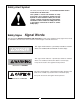
Safety Alert Symbol This Safety Alert Symbol means: “ATTENTION! BECOME ALERT! YOUR SAFETY IS INVOLVED!” This symbol is used to call attention to safety precautions that should be followed by the operator to avoid accidents. When you see this symbol, carefully read the message that follows and heed its advice. Failure to comply with safety precautions could result in death or serious bodily injury.
IMPORTANT SAFETY PRECAUTIONS This symbol is used to call attention to safety precautions that should be followed by the operator to avoid accidents. When you see this symbol, carefully read the message that follows and heed its advice. Failure to comply with safety precautions could result in serious bodily injury.
SAFETY PRECAUTIONS CONTINUED 12. DO NOT dig under stabilizers or tractor backhoe. Soft ground or sandy soil can cause cave-ins. 13. KEEP BUCKET away from the stabilizer area to avoid possible stabilizer damage. 14. ALWAYS swing bucket uphill to dump when on a hillside and keep loaded bucket low. 15. SET BRAKES and block wheels when operating on hills and banks to avoid dangerous runaway. 16. WATCH for overhead wires. DO NOT touch wires with any part of the backhoe. 17.
IMPORTANT FEDERAL LAWS AND REGULATIONS* CONCERNING EMPLOYERS, EMPLOYEES AND OPERATIONS. *(This section is intended to explain in broad terms the concept and effect of the following federal laws and regulations. It is not intended as a legal interpretation of the laws and should not be considered as such). U.S. Public Law 91-596 (The Williams-Steiger Occupational Safety and Health Act of 1970) OSHA This Act Seeks: “...
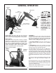
GENERAL OPERATION Figure 1 Dipper-Stick Swing Lock Pin Location Bucket Link Boom Boom Transport Lock Pin Location Bucket Mainframe Stabilizer Cylinder CAUTION To avoid possible injury, observe the following safety rules BEFORE OPERATING the backhoe: 1. BE SURE area is clear of underground utilities or other hazards. 2. POSITION barricade around work area. 3. PROVIDE adequate front end weight to counter-balance tractor at all times.
Figure 3 Safety Locks Figure 3a Lock Pins Storage Tubes Swing Lock Pin Boom Transport Lock Pin SWING LEFT AND RAISE the boom by moving the control lever back and to the left. In general, the direction of movement of a control lever corresponds to the movement of the operating member. SWING RIGHT AND LOWER the boom by moving the lever forward and to the right. OPERATING THE BACKHOE SWING RIGHT AND RAISE the boom by moving the lever back and to the right.
Location: Back Of Control Panel It is not difficult to become an efficient operator. Control lever operating decal is located on back of the control console. Study this decal. It will assist you in becoming familiar with the controls. operator to save time in clearing the excavation. This dual operation of controls will speed and simplify the digging operation.
4. USE accessory lights and SMV emblem when traveling on highways. CAUTION To avoid possible injury, observe the following safety rules when transporting the backhoe: Before leaving backhoe operator’s seat, position the backhoe for transport by raising boom, crowding dipperstick in, swinging to center and raising the stabilizers. 1. ALWAYS engage safety locks as shown on Figs. 1 and 3 when transporting backhoe. 2. TRAVEL SLOWLY over rough terrain, on hillsides, and around curves to prevent tipping.
General Operations As the pile is approached, dump the bucket. When the bucket is empty, the dipperstick and bucket are in position to resume digging upon return to the trench. FILLING THE BUCKET Control the bucket attitude throughout the digging cycle to keep teeth at the proper angle for best penetration. This will minimize dragging and scraping the bucket through the ground.
General Operations MISCELLANEOUS When finishing straight walls or bellholes in sandy soil, use a platform under the rear tires and the stabilizers. The platform distributes the load over a larger area and lessens the possibility of a cave-in. The platform also tends to keep the unit from creeping rearward if hard digging is encountered. SIDE SLOPE EXCAVATING OR TRENCHING Dig with the backhoe uphill whenever possible.
SERVICE fully several times to purge the system of air. Hydraulic System Hoses Oil leaks in the pressure side of the system can be located by carefully inspecting the external area of the hoses and fittings. Check the return side of the system for leaks by examining the oil in the reservoir. If air is being drawn into the system, the oil will contain air bubbles and appear to foam. When tightening connections, always use two wrenches. IMPORTANT: Do not over-tighten fittings.
TOOTH REPLACEMENT LUBRICATION Bolt-On tooth points, when worn, can be replaced by removing the hardware that connects it to the cutting edge. Install new tooth and replace hardware if necessary. (Figure 5) IMPORTANT: Avoid excessive greasing. Dirt collects on exposed grease and increases wear greatly. After greasing, wipe off excessive grease from fittings. Roll-Pinned tooth points, when worn, can be replaced by driving out the roll pin with a hammer and punch.
REMOVAL FROM TRACTOR - STORAGE Figure 9 Backhoe Partially Extended Backhoe Fully Extended Blocking For Support CAUTION The backhoe is self-assisting during the installation and removal procedures. For removal and storage, follow these steps: Make sure tractor PTO is disengaged and engine shut off before disconnecting pump or hydraulic lines. a. On PTO pump self-contained systems, the pump should be removed from the PTO shaft. The hydraulic system should always remain complete.
Figure 10 STABILIZER PADS The backhoe is supplied with flip-over stabilizer feet as standard equipment. They are suitable for most backhoe work and generally are all that is ever required. However, foot pad kits are available as options. These kits bolt to the standard feet and increase the versatility of the backhoe. See Figure 10.
TROUBLESHOOTING (Continued) Problem Cause Correction Machine loses power after operating satisfactorily initially Diverter valve on prime move leaking or bypassing oil internally through valve to reservoir Diverter valve may need rebuilding or replacing. Excessive back pressure Relieve condition. Restriction may be from outlet to reservoir. Relief pressure will have to be checked and corrections made. Backhoe system pressure is 2400 PSI.
Troubleshooting (Continued) Problem Loss of power in any one cylinder, including lift and crowd Cause Worn or damaged rod seals on cylinder; external leaks Correction Repack cylinder. Rebuild cylinder, replacing damaged parts as necessary. Spool not moved to full stroke Check spool travel - should be .26” either way, or a total of .52”. Clean relief carefully but do not disturb its pressure setting as it cannot be field calibrated, or replace cartridge. Replace the control valve.
Troubleshooting (Continued) Problem Slow operation of machine (lack of power) all cylinders Cause Relief valve setting in backhoe control valve too low or defective Correction Relief pressure will have to be checked and corrections made. Backhoe system pressure is 2400 PSI. Relief valve may need cleaning and overhauling, or entire cartridge must be replaced. Spongy or jerking action of cylinders and/or noisy operation Low oil supply in reservoir Fill to proper level.
Troubleshooting (Continued) Problem Cause Correction Leaky cylinders Oil is bypassing cylinder piston, scored piston, worn piston packing, or defective piston assembly Scored piston rods and worn guides in cylinder Replace or rebuild the cylinder; replace damaged parts. Bent piston rod in cylinder Replace or rebuild the cylinder; replace damaged parts. Repack cylinder. Rebuild cylinder, replacing damaged parts as necessary.
Troubleshooting (Continued) Problem Cause Correction Unable to push valve spool in Paint on valve spool; sticking valve spool or scored valve spool Clean valve spool. Binding is usually caused from an overtightened plug, mounting bolt, fitting in valve body or tie rod bolt. If a plug or fitting in the valve body is leaking, do not overtighten in an effort to stop leak. This will distort body casting and cause spools to bind.
Figure 11 VALVE REPAIR Position Pin Bushing FLOAT ASSEMBLY Spring Bushing SPOOL CONTROL KIT 7. Thoroughly clean the O-ring counterbores and the ground surfaces of each section. Place O-ring seals, ordered as a kit, in proper counterbores. For better sealing, it is recommended that all O-rings used in the counterbores be replaced with new parts.
1. Remove control valve from the backhoe. B. Float Kit Only: 2. Thoroughly clean the exterior of the valve before beginning disassembly procedures. All parts inside cap are lubricated with synthetic base grease grade NLGI2. Install new o-ring seal over valve spool and insert seal in counterbore. Replace backup washer, control bushing, control spring, control bushing and positioner pin, being careful to orient items per Figure 11. 3. At the BOTTOM of the valve remove screws, cap and spool control kit.
3. Remove parts bag containing bucket pins from backhoe. Attach bucket (D) to dipperstick (B) using one pin, 3/8” bolt, and locknut. 6. Attach stabilizer cylinders (H) to stabilizers (F) using pins and hardware from parts bag. 7. Using caution to prevent tipping, raise mainframe (G) with hoist to a height of approximately 17” and remove skid. Block mainframe (G) and swing frame (J) securely. 4. Attach bucket link (E) to bucket, using same hardware as listed for step #3. 5.
IMPORTANT: Tractor lower links must be kept free of lifting forces at all times after installation of the attaching kit by keeping tractor quadrant lever in the lowered position. 3-Point Hitch Linkage 2165 & 2175 The backhoe is mounted on the tractor lower link arms and an adjustable upper link is supplied to replace the tractor upper link. A set of stabilizer arms is included. They bolt from the adjustable upper link to the backhoe mainframe, locking the hoe rigidly in one position.
using 3/4 x 4-1/2” bolt (15), flat washers (9), lockwasher (10) and nut (11). Use hoist to raise or lower backhoe slightly until a hole in the upper bar aligns with a hole in the upper braces. See Figure 14. ASSEMBLY (Refer to Figures 14 & 15) IMPORTANT: Tighten all hardware to the torque requirements specified in the torque chart. WARNING 6.
Figure 15 (2165 &2175) 22 11 21 11 10 9 10 7 9 14 1 12 13 11 10 9 9 23 24 20 9 7 15 2 19 9 18 8 17 17 16 6 3 5 4 2185/2195 3-POINT HITCH LINKAGE 3-Point Hitch Linkage IMPORTANT- Tractor lower links must be kept free of lifting forces at all times after installation of the attaching kit by keeping tractor quadrant lever in the lowered position. The backhoe is mounted on the tractor lower link arms and an adjustable upper link is supplied to replace the tractor upper link.
Figure 16 (2185 & 2195) 1 11 10 9 22 21 11 10 9 7 14 12 13 11 10 9 24 9 23 9 7 9 20 15 2 19 18 8 17 17 6 5 ASSEMBLY 16 3 4 5. Secure upper bar (14) between upper braces (7) using 3/4 x 4-1/2” bolt (15), flat washers (9), lockwasher (10) and nut (11). Use hoist to raise or lower backhoe slightly until a hole in the upper bar aligns with a hole in the upper braces. See Figure 16. IMPORTANT: Tighten all hardware to the torque requirements specified in the torque chart on page 45.
Figure 17 Upper Bar Tractor Upper Link Bracket Upper Brace Link Weldment Tractor Lower Link C Backhoe Mainframe PTO PUMP KITS (Optional) General Description Elbow may have to be rotated slightly to allow fill tube to be installed so that its open end is located just behind foot platform to right of operator’s seat tower. Install breather cap with dipstick (18) onto fill tube. The PTO Pump Kits consist of those parts required to power the backhoe from the tractor’s PTO shaft.
identical fitting to “In/Pressure” port of bulkhead connection. Orient fittings so that free ends of fittings point horizontally toward center of backhoe. requires 7 gallons of fluid. Fill reservoir with recommended fluid to correct level, referring to Service Section in Backhoe Operator’s Manual. DO NOT overfill reservoir or oil may be forced out through breather cap during backhoe operation. 6.
27 1, 6, 4 Figure 18 15 35 26 Torque Plate Shown In “Up” Position Around 3-Point Hitch Link 32 18 23 28 17 21 34 2 5 22 16 7 10 32 26 31 Torque Plate In “Down” Position 8 11 19 5 7 20 2 24 29 3 20 14 9 12 9 13 14 30 25 33 valve or other accessory valve is connected to the tractor system, and whether the tractor has an opencenter system (constant pumping of oil to control valve and back to reservoir) or a closed-center system (no flow of oil until there is a demand at one hydraulic cy
Since the Power Beyond Kit is used with open-center tractor hydraulic systems, oil constantly flows from the pump, through the backhoe valve and the loader valve or other accessory valve, and then to the reservoir. See further in this manual for instructions on proper assembly. IMPORTANT: Never connect the return hose to a tractor remote coupler which can be pressurized. Accidental pressurization can cause serious damage to backhoe valve. 4.
occurs. As the system pressure is approaching maximum, the pump is also beginning to stroke back for less and less fluid delivery. At maximum pressure, the pump is completely destroked and there is no delivery. Hydraulic Hook-Up (2175, 2185, 2195) For Tractors With Closed-Center Hydraulic Systems (Figure 21) There are two basic types of hydraulic systems, opencenter and closed-center.
POWER BEYOND KITS FOR TRACTORS WITH OPEN-CENTER HYDRAULIC SYSTEMS When connecting the Great Bend backhoe valve to a Great Bend front end loader valve, the input pressure line from the tractor will be connected to the loader valve first. The power beyond pressure line will be connected to the input pressure port of the backhoe valve. In order to properly plumb the system, the loader valve will require converting to a power beyond valve.
GREAT BEND BACKHOE & GREAT BEND LOADER VALVE Figure 23 NOTE: Large loader valve (Walvoil) shown. Small loader valve porting is different. Refer to loader operator’s manual for different valves.
sure port of the loader valve. The power beyond kit for the backhoe being assembled must be ordered as a separate item from Great Bend. SECOND PROCEDURE ASSEMBLY OF A GREAT BEND BACKHOE TO A NON GREAT BEND LOADER VALVE OR - GREAT BEND BACKHOE TO LOADER VALVE USING PTO PUMP KIT OPTION Assembly 1. Remove the front cover that encloses the backhoe valve within the control console.
FLOW DIVIDER KIT (Optional) Backhoe Mounted to Tractor General Description 1. Assemble three 90° male adapters (10) to flow divider valve as shown in Figure 25. The Flow Divider Kit consists of those parts required to power the backhoe from tractors or skid steer loaders that have hydraulic flow rates above 12 gallons per minute (gpm). It includes the flow divider valve, hydraulic hoses to connect the valve to the backhoe, and adapter fittings.
Tractors with an auxiliary hydraulic flow greater than 15 gpm Testing Backhoe Hydraulic Hook-Up 1. Start tractor engine. Connect JIC swivel run tee (9) to 90° male adapter (10) on “K2” port on valve as shown in Figure 27. 2. Set parking brake and engage tractor remote hydraulics so that oil flows to backhoe. NOTE! Consult tractor Operator’s Manual for proper operation. IMPORTANT - The location of the JIC swivel run tee will ensure that proper flow is provided to the backhoe for smooth operation.
Skid Steers with an auxiliary hydraulic flow of 15 gpm or less - Figure 29 nection and JIC swivel run tee (9) on flow divider valve. Assemble straight male adapter (6) to “K3” port on valve as shown in Figure 29. Assemble JIC swivel run tee (9) to straight male adapter (6). Assemble 90° male adapter (10) to “K2” port on valve. 8.
Figure 29 FOR SKID STEER HYDRAULIC FLOW OF 15 GPM OR LESS 8 Return Line To Skid Steer 9 10 6 K3 K2 7 5 To Backhoe Bulkhead “Return” Connection 11 10 To Backhoe Bulkhead “Pressure” Connection Pressure Line From Skid Steer 7 8 Figure 30 FOR SKID STEER HYDRAULIC FLOW GREATER THAN 15 GPM Return Line To Skid Steer 9 6 10 K2 K3 7 5 To Backhoe Bulkhead “Return” Connection Pressure Line From Skid Steer 11 To Backhoe Bulkhead “Pressure” Connection 7 41 10
BACKHOES - DIMENSIONS AND SPECIFICATIONS SERIES 2165 2175 2185 2195 Maximum Digging Depth 7’0” 8’0” 9’0” 10’0” A. Digging Depth (two foot flat bottom) 6’6” 7’6” 8’6” 9’6” B. Swing Arc 180° 180° 180° 180° C. Loading Height (bucket at 60°) 4’4” 5’4” 6’8” 7’6” D. Reach from Center Line of Swing Pivot 9’4” 10’ 11’1” 12’4” E. Transport Height (maximum) 5’6” 6’7” 6’11” 8’0” F. Bucket Rotation 180° 180° 180° 180° G. Loading Reach (bucket at 60°) 4’6” 3’9” 4’1” 4’7” H.
REPOSITION STABILIZER CYLINDERS BEFORE REMOVING BACKHOE FROM SHIPPING PALLET Cylinder ports must be pointing upward and hoses routed above the cylinder to mainframe pivot pin connection. Palletized backhoe as shipped from factory. Remove stabilizers and fasteners from pallet. Position stabilizer between mounting lugs and pin into place. Cut plastic ties from rod ends of hydraulic cylinders, swing down and pull rod end out to align with stabilizer mounting lugs. Pin into place with provided fasteners.
SAFETY DECALS The safety of the operator was a prime consideration in the design of the backhoe. Proper shielding, convenient controls, simple adjustments and other safety features have been built into this implement. The following decals are located on the backhoe. Keep decals clean and replace them immediately if they are missing. Contact your dealer or Great Bend for replacements.
TORQUE SPECIFICATIONS Proper toque for American fasteners used on Great Bend equipment. Recommended Torque in Foot Pounds (Newton Meters).* AMERICAN Bolt Head Markings SAE Grade 2 (No Dashes) SAE Grade 5 (3 Dashes) ” lt Bo ter “B e m Dia Wrench Size “A” SAE Grade 8 (6 Dashes) METRIC Wrench Size “A” WRENCH SIZE (IN.) “A” BOLT DIAMETER (IN.
® BUSH HOG, L.L.C. P.O.