BUSH HOG Backhoe Models ® CBH60 / CBH70 / CBH80 Operator’s Manual ASSEMBLY l OPERATION l MAINTENANCE 06/09 Rev. 2 $4.
CONGRATULATIONS! You have invested in the best implement of its type on the market today. The care you give your Bush Hog implement will greatly determine your satisfaction with its performance and its service life. We urge a careful study of this manual to provide you with a thorough understanding of your new implement before operating, as well as suggestions for operation and maintenance. If your manual should become lost or destroyed, Bush Hog will be glad to provide you with a new copy.
Operator’s Manual BUSH HOG BACKHOE MODELS CBH60, CBH70, CBH80 SECTION/PARA TABLE OF CONTENTS SECTION/PARA PAGE PAGE Tooth Replacement . . . . . . . . . . . . . . . . . . . . . 16 Lubrication . . . . . . . . . . . . . . . . . . . . . . . . . . . . 16 Removal / Storage . . . . . . . . . . . . . . . . . . . . . . 17 Stabilizer Pads . . . . . . . . . . . . . . . . . . . . . . . . . 18 Hydraulic Trouble Shooting . . . . . . . . . . . . . . . 18 Valve Repair CBH 60 . . . . . . . . . . . . . . . . . . . .
LIMITED WARRANTY OOOOOOOOOOOOOOOOOOOOOOOOOOOOOOO Bush Hog warrants to the original purchaser of any new Bush Hog equipment, purchased from an authorized Bush Hog dealer, that the equipment be free from defects in material and workmanship for a period of one (1) year for non-commercial, state, and municipalities’ use and ninety (90) days for commercial use from date of retail sale. The obligation of Bush Hog to the purchaser under this warranty is limited to the repair or replacement of defective parts.
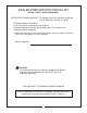
DEALER PREPARATION CHECK LIST CBH60 - CBH70 - CBH80 BACKHOES BEFORE DELIVERING MACHINE - The following check list should be completed. Use the Operator’s Manual as a guide. q q q q q Machine properly assembled. All safety decals readable (See decal page). All bolts tightened to torque specifications given in the torque chart. Machine operates properly. Operator’s manual has been delivered to owner and he has been instructed on the safe and proper use of the backhoe.
Safety Alert Symbol This Safety Alert Symbol means: “ATTENTION! BECOME ALERT! YOUR SAFETY IS INVOLVED!” This symbol is used to call attention to safety precautions that should be followed by the operator to avoid accidents. When you see this symbol, carefully read the message that follows and heed its advice. Failure to comply with safety precautions could result in death or serious bodily injury.
IMPORTANT SAFETY PRECAUTIONS This symbol is used to call attention to safety precautions that should be followed by the operator to avoid accidents. When you see this symbol, carefully read the message that follows and heed its advice. Failure to comply with safety precautions could result in serious bodily injury.
SAFETY PRECAUTIONS CONTINUED 12. DO NOT dig under stabilizers or tractor backhoe. Soft ground or sandy soil can cause cave-ins. 13. KEEP BUCKET away from the stabilizer area to avoid possible stabilizer damage. 14. ALWAYS swing bucket uphill to dump when on a hillside and keep loaded bucket low. 15. SET BRAKES and block wheels when operating on hills and banks to avoid dangerous runaway. 16. WATCH for overhead wires. DO NOT touch wires with any part of the backhoe. 17.
SAFETY DECALS The safety of the operator was a prime consideration in the design of the backhoe. Proper shielding, convenient controls, simple adjustments and other safety features have been built into this implement. The following decals are located on the backhoe. Keep decals clean and replace them immediately if they are missing. Contact your dealer or Bush Hog for replacements.
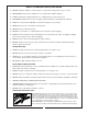
IMPORTANT FEDERAL LAWS AND REGULATIONS* CONCERNING EMPLOYERS, EMPLOYEES AND OPERATIONS. *(This section is intended to explain in broad terms the concept and effect of the following federal laws and regulations. It is not intended as a legal interpretation of the laws and should not be considered as such). U.S. Public Law 91-596 (The Williams-Steiger Occupational Safety and Health Act of 1970) OSHA This Act Seeks: “...
GENERAL OPERATION Figure 1 ! CAUTION Swing Lock Pin Location Bucket Link Boom Mainframe Stabilizer Cylinder Stabilizer Dipper-Stick Boom Transport Lock Pin Locations CONTROLS The backhoe has two major control levers plus the stabilizer control levers. These controls are located on the control console directly ahead of the operator. See Figure 2. The following is a list of the controls, with the function of each, reading from left to right.
Figure 3a Figure 3 Safety Locks Swing Lock Pin Lock Pins Storage Locations Boom Transport Lock Pin Location In general, the direction of movement of a control lever corresponds to the movement of the operating member. SWING LEFT AND RAISE the boom by moving the control lever back and to the left. SWING RIGHT AND LOWER the boom by moving the lever forward and to the right. OPERATING THE BACKHOE ! CAUTION SWING RIGHT AND RAISE the boom by moving the lever back and to the right.
Location: Back Of Control Panel This dual operation of controls will speed and simplify the digging operation. Normally the two or more movements will not be equal or even simultaneous, but as the pressure within the cylinders changes, and the resistance on an operating member of the hoe lessens, it will begin to move. It is balancing the force of one member against the other. It is not difficult to become an efficient operator. Control lever operating decal is located on back of the control console.
4. USE accessory lights and SMV emblem when traveling on highways. ! CAUTION To avoid possible injury, observe the following safety rules when transporting the backhoe: Before leaving backhoe operator’s seat, position the backhoe for transport by raising boom, crowding dipperstick in, swinging to center and raising the stabilizers. 1. ALWAYS engage safety locks as shown on Figs. 1 and 3 when transporting backhoe. 2. TRAVEL SLOWLY over rough terrain, on hillsides, and around curves to prevent tipping.
General Operations As the pile is approached, dump the bucket. When the bucket is empty, the dipperstick and bucket are in position to resume digging upon return to the trench. IMPORTANT: Avoid constant jarring or hammering-type contact between the spoil pile and the loaded bucket, as this may cause premature wear to the backhoe pins and bushings. FILLING THE BUCKET Control the bucket attitude throughout the digging cycle to keep teeth at the proper angle for best penetration.
MISCELLANEOUS General Operations When finishing straight walls or bellholes in sandy soil, use a platform under the rear tires and the stabilizers. The platform distributes the load over a larger area and lessens the possibility of a cave-in. The platform also tends to keep the unit from creeping rearward if hard digging is encountered. SIDE SLOPE EXCAVATING OR TRENCHING Dig with the backhoe uphill whenever possible.
SERVICE ! CAUTION Hydraulic System Hoses To avoid possible injury, observe the following safety rules WHEN SERVICING the backhoe: Oil leaks in the pressure side of the system can be located by carefully inspecting the external area of the hoses and fittings. 1. ENGAGE safety locks as shown in Figures 1 & 3 before servicing the backhoe. Check the return side of the system for leaks by examining the oil in the reservoir.
Tightening Nuts and Bolts TOOTH REPLACEMENT The bucket tooth points are shelf-sharpening and will require little attention; however these points on the bucket shanks can be replaced when they become badly worn or broken. If a tooth shank breaks off, becomes damaged or lost so that it cannot hold a tooth point, a new shank should be welded to the bucket in its place. Periodically, check to be sure all bolts and nuts are tight. See torque chart, page 51 .
REMOVAL FROM TRACTOR - STORAGE Figure 9 Backhoe Fully Extended Place Blocking Under Backhoe Frame For Support The backhoe is self-assisting during the installation and removal procedures. For removal and storage, follow these steps: ! CAUTION 1. Install the swing safety lock pin as shown in Figures 1 and 3. 2. Stretch out the boom, dipper stick and bucket as shown in Figure 9. Lower the bucket to the ground so that it rests there solidly. 3. Raise the backhoe operator’s seat to the raised position.
STABILIZER PADS Figure 10 The backhoe is supplied with flip-over stabilizer feet (Excluding Model CBH60) as standard equipment. They are suitable for most backhoe work and generally are all that is ever required. However, foot pad kits are available as options. These kits bolt to the standard feet and increase the versatility of the backhoe. See Figure 10.
TROUBLESHOOTING (Continued) Problem Machine loses power after operating satisfactorily initially Loss of power in lift or crowd cylinder, but other cylinders function properly Cause Diverter valve on prime move leaking or bypassing oil internally through valve to reservoir Correction Diverter valve may need rebuilding or replacing. Relief valve setting in backhoe control valve too low or defective Relief pressure will have to be checked and corrections made.
Troubleshooting (Continued) Problem Loss of power in any one cylinder, including lift and crowd (cont.) Cause Correction Bent piston rod in cylinder Replace or rebuild the cylinder; replace damaged parts. Scored piston rods and worn guides in cylinder Worn or damaged rod seals on cylinder; external leaks Loss of power in swing cylinders, but other cylinders functioning properly. Replace or rebuild the cylinder; replace damaged parts. Repack cylinder.
Troubleshooting (Continued) Problem Maximum swing action cannot be obtained Slow operation of machine (lack of power) all cylinders Cause Correction Something jamming the swing linkage Remove interference. Oil viscosity too heavy, or oil is not at operating temperature Use recommended hydraulic fluid. Run machine until oil reaches operating temperature. Bent piston rod in cylinder Low oil supply in reservoir Fill to proper level. Insufficient pumping Advance engine throttle.
Troubleshooting (Continued) Problem Lift, crowd or bucket cylinders drop under load when control spools shifted from neutral Load drops or settles Cause Problems involving the control valve (cont.) Loose oil line connections, leaks in line or broken lines Oil is bypassing cylinder piston, scored piston, worn piston packing, or defective piston assembly Everything must be clean and free of dirt during the oil line removal and replacement, and during any cylinder work.
Troubleshooting (Continued) Problem Leaky valve Sticky valve spool spool in Cause Correction Ball in anti-cavitation check valve is stuck or not seating properly. Clean anti-cavitation valve carefully, being sure that checks move freely and seat properly, or replace cartridge. Paint on valve spool; sticking valve spool or scored valve spool Paint on valve spool; sticking valve spool or scored valve spool Bent spool Clean valve spool.
Troubleshooting (Continued) Problem Unable to push valve spool in Spring centered spools do not return to neutral Cause Correction Foreign particles Clean system and valve. Bent spool Replace with new spool section. Misalignment of control handle linkage Paint on valve spool; sticking valve spool or scored valve spool Oil leakage past spool seal into spool cap Broken return springs Check linkage for binding condition. Clean valve spool.
MODEL CBH 60 MONOBLOCK VALVE REPAIR - DISASSEMBLY 6. Install new seals: A. Spring-Centered Bonnet Assembly Only: Replacing Spools Seals: Lightly oil new O-ring seal. Slide seal over valve spool and insert weal in counter bore. Replace backup washer and seal retainer. Note: For the purpose of these instructions we will consider the control handle side of the valve as the FRONT, and the opposite side as the BACK. B. Float Bonnet Assembly Only: 1. Remove control valve from the backhoe.
MODEL CBH 70, CBH 80 of the end sections on a flat surface. To obtain proper alignment of end sections relative to the spool sections apply downward pressure to the end sections; snug tie rod nuts to about 10 ft. lbs. VALVE REPAIR - DISASSEMBLY Replace Center Section Assemblies: Finally torque the two 1/2” nuts to 14 ft. lbs.; finally torque the 9/16” nut to 33 ft. lbs. Check for proper spool movement.
11. Lightly oil new O-ring seal. Slide O-ring seal over valve spool and insert in seal counter bore. Replace back-up washer, and seal plate retainer. 8. At the FRONT of the valve remove all parts connected to the spool (handle, linkage, etc.). 9. At the FRONT of the valve remove seal plate retainer, back-up washer and spool O-ring seal. 12. Reattach all parts connected to the spool (handle, linkage, etc.). 10. Thoroughly clean counter bore.
Figure 13 DIPPERSTICK GUIDE LINK BOOM STABILIZER CYLINDER BUCKET LINK BUCKET MAINFRAME STABILIZER LEG ASSEMBLY - CBH 60, CBH 70, CBH 80 Model CBH 60 3. Remove plastic bag containing bucket pins from backhoe. Attach bucket to dipperstick using one pin, bolt, lock nuts, and shims as needed to take up gap between dipperstick and bucket. The backhoe has been partially disassembled and strapped to a skid for shipping purposes.
MOUNTING KITS AND OPTIONAL KITS ASSEMBLY 3-POINT HITCH LINKAGE FOR CBH 60 & CBH 70 General Description 3-Point Hitch Linkage Mounting Backhoe to Tractor IMPORTANT: Tractor lower links must be kept free of lifting forces at all times after installation of the attaching kit by keeping tractor quadrant lever in the lowered position. The backhoe is mounted on the tractor lower link arms and an adjustable upper link is supplied to replace the tractor upper link. A set of stabilizer arms is included.
Model CBH60 Backhoe 4. Install Seat Assembly from base backhoe to Seat Upper Weldment (23) using hardware provided with base backhoe, consisting of four 1/2NC x 1-3/4” Carriage Bolts, Lockwashers, and Nuts. ATTACHING KIT INSTRUCTIONS 3-POINT HITCH LINKAGE & HYDRAULIC HOOKUP TO TRACTOR HYDRAULIC SYSTEMS 5. Tighten and torque all hardware installed. 6. Back tractor close to the backhoe.
20 30 17 18 3 15 21 15 6 10 16 24 23 18 9 31 30 17 22 16 1 13 28 25 20 2 14 16 11 14 11 4 32 16 28 27 14 11 26 16 31 29 19 5 16 27 7 Model CBH60 Backhoe ATTACHING KIT INSTRUCTIONS 3-POINT HITCH LINKAGE Figure 14
MODEL CBH70 BACKHOE ATTACHING KIT INSTRUCTIONS 4. Install Bushing (13) or Bushing (16) in the Upper Bar (20) that most closely matches the diameter of the tractor upper link pin. No bushing is necessary for Category II tractors. 3-POINT HITCH LINKAGE & HYDRAULIC HOOK-UP TO TRACTOR HYDRAULIC SYSTEMS. General Description Mounting and hydraulics kits do not include hoses which connect the backhoe control valve to the tractor hydraulic system.
MODEL CBH70 BACKHOE ATTACHING KIT INSTRUCTIONS 3-POINT HITCH LINKAGE Figure 15 33
MODEL CBH80 BACKHOE ATTACHING KIT INSTRUCTIONS 4. Install Bushing (13) or Bushing (16) in hole of the Upper Bar (17) that most closely matches the diameter of the tractor upper link pin. No bushing is necessary for Category II tractors. 3-POINT HITCH LINKAGE & HYDRAULIC HOOKUP TO TRACTOR HYDRAULIC SYSTEMS 5. Secure Upper Bar (17) between Upper Braces (18) using 3/4 x 4-1/2” Bolt (3), Flat Washers (10), Lockwasher (9) and nut (7).
MODEL CBH80 BACKHOE ATTACHING KIT INSTRUCTIONS 3-POINT HITCH LINKAGE Figure 16 35
PTO PUMP & RESERVOIR KIT INSTALLATION General Description CBH70 4.5 GPM Pump 7. Reinstall Filter Element to the Filter Base. 8. Assemble Pump Plate (26) to Pump (11) using two 3/8” NF x 1-3/4” Bolts (1), Lockwashers (8), and Nuts (4). Pump Plate may have to be readjusted later when installed on tractor PTO Shaft. The Plate may need to be turned 180 degrees to provide proper engagement with tractor drawbar and have adequate clearances.
IMPORTANT - When installing the backhoe, do not let the Swing Cylinders interfere with the backhoe pump, or have the hydraulic lines become entangled in any part of the backhoe or tractor. Make sure both Pressure and Suction Lines are free from kinks or twists to reduce back pressure and excessive heat build-up. CBH 70 4.
General Description CBH 80 6.1 GPM Pump may need to be turned 180 degrees to provide proper engagement with tractor drawbar and have adequate clearances. The PTO Pump Kit consists of those parts required to power the backhoe from the tractor’s PTO shaft. It includes the PTO pump and adapter, reservoir, filtration system, hydraulic hoses, and fittings. In addition, it includes a pump plate which attaches to the tractor’s drawbar and keeps the pump from turning the PTO shaft. 9.
IMPORTANT - When installing the backhoe, do not let the Swing Cylinders interfere with the backhoe pump, or have the hydraulic lines become entangled in any part of the backhoe or tractor. Make sure both Pressure and Suction Lines are free from kinks or twists to reduce back pressure and excessive heat build-up. CBH 80 6.
1. OPEN-CENTER SYSTEM WITH LOADER VALVE OR OTHER ACCESSORY VALVE CONNECTED TO THE TRACTOR HYDRAULIC SYSTEM port of the tractor remote couplers or directly to the tractor valve. The return hose (B) should be connected from the tank (return) port on the backhoe to a port on the reservoir, as shown in Figure 19. When a loader valve or other accessory valve must be connected to the tractor hydraulic system in addition to the backhoe control valve, a Power Beyond Kit is required.
Hydraulic Hook-Up (CBH 80) For Tractors With Closed-Center Hydraulic Systems (Figure 21) exceed 2800 PSI. 3. A closed-center plug in the backhoe control valve to make it a non-circulating or a demand type system. There are two basic types of hydraulic systems, open-center and closed-center. The open-center system constantly pumps oil through the hydraulic cylinder operating valves and returns the oil to the reservoir.
POWER BEYOND KITS FOR TRACTORS WITH OPEN-CENTER HYDRAULIC SYSTEMS FIRST PROCEDURE General Description A power beyond application is required to convert a hydraulic valve so that pressurized oil can be directed to another “open center” valve. This allows the backhoe valve and a loader valve, or other accessory, to be connected to the tractor hydraulic system simultaneously, without the inconvenience of using a flow diverting valve. ASSEMBLY OF A BUSH HOG BACKHOE TO A BUSH HOG LOADER VALVE.
Figure 22 BUSH HOG BACKHOE & BUSH HOG LOADER VALVE NOTE: Large loader valve (Walvoil) shown. Small loader valve porting is different. Refer to loader operator’s manual for different valves.
SECOND PROCEDURE The following instructions are to be used to connect the backhoe valve in line with a loader valve that is not a Bush Hog loader valve. When connecting the Bush Hog backhoe valve to a valve other than one obtained from Bush Hog, the input pressure line from the tractor will be connected to the pressure port on the backhoe first. In order to properly plumb the system, the backhoe valve will require converting to a power beyond valve.
Power Beyond – Model CBH60 - FIGURE 24 1. Remove the cover that encloses the backhoe valve within the control console. 2. Disconnect Return Hose from 90 degree Adapter Union located on right hand side of control valve. 3. Remove 90 degree Adapter Union from control valve. 4. Install 1/4" BSPP Pipe Plug internally into the port opening. Tighten. Reinstall 90 degree Adapter Union into right hand side of control valve. 5. Reconnect Return Hose to 90 degree Adapter Union. 6.
Power Beyond – Model CBH70 & CBH80 - FIGURE 25 1. Remove Plug from underside of Right Hand Valve End Cover. 2. Install “Shut Off” Plug into the port opening. Torque Plug to 32 ft-lbs. 3. Remove Plug from Upper port on front side of Right Hand Valve End Cover. 4. Install 90 degree Adapter Union into Right Hand End Cover. 5. Assemble 45 degree Adapter Union into 90 degree Adapter Union, directing it rearward. 6. Connect hydraulic hose (supplied by customer) to 45 degree Adapter Union.
MECHANICAL THUMB INSTRUCTIONS - FIGURE 26 Thumb Operation The Mechanical Thumb is used for picking up objects and securing them between the thumb and the bucket. Large objects which can include rocks and logs when grasped, will increase momentum of backhoe as it is swung side to side. Do not make sudden start and stops. Be careful lifting and moving long items such as tree limbs, which will extend beyond the normal backhoe swing arc area. Improper usage will damage backhoe and/or thumb.
FIGURE 26 2 7 4 4 6 10 11 1 8 4 5 MECHANICAL THUMB ASSEMBLED 48 4 3 9 3
REPOSITION STABILIZER CYLINDERS BEFORE REMOVING BACKHOE FROM SHIPPING PALLET Cylinder ports must be pointing upward and hoses routed above the cylinder to mainframe pivot pin connection. Backhoe is shipped palletized from factory. Remove stabilizers and fasteners from pallet. Position stabilizer between mounting lugs and pin into place. Cut plastic ties from rod ends of hydraulic cylinders, swing down and pull rod end out to align with stabilizer mounting lugs. Pin into place with provided fasteners.
BACKHOES - DIMENSIONS AND SPECIFICATIONS SERIES Maximum Digging Depth A. Digging Depth (two foot flat bottom) B. Swing Arc C. Loading Height (bucket at 60°) CBH60 7-1/4 Foot 8-1/4 Foot 74.5” 86.5” 98.5” 76” 150° I. Undercut J. Stabilizer Spread, up position K. Stabilizer Spread, down position Bucket Cylinder Digging Force Dipperstick Cylinder Digging Force` 180° 73.5” 66” 82” F. Bucket Rotation H. Transport Overhang 87.5” 60” 104” G.
TORQUE SPECIFICATIONS AMERICAN Proper toque for American fasteners used on Bush Hog equipment. Recommended Torque in Foot Pounds (Newton Meters).* Bolt Head Markings WRENCH SIZE (IN.) “A” BOLT DIAMETER (IN.
2501 Griffin Ave. l Selma, AL 36703 Telephone (334) 874-2700 l www.bushhog.