
Data Sheet

For product data sheets, visit www.cooperbussmann.com/DatasheetsEle
234
High Speed Fuses
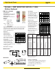
Ferrule — FWP 690V/700V (IEC/UL): 1-50A,
Striker Optional
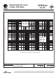
Dimensions - mm (in)
51 (2.00")
59 (2.323")
13 (0.511")
14.3
(0.563")
5 (0.197")
FWP (14 x 51mm)
Specifications
Description: Ferrule style high
speed fuses with and without
indicating striker.
Dimensions: See dimensions
illustrations.
Ratings:
Volts: — 690Vac (IEC)
— 700Vac (UL)
— 800Vdc (5-50A)
Amps: — 1-50A
IR: — 200kA RMS Sym.
— 50kA @800Vdc
Agency Information: CE, UL Recognition JFHR2.E91958,
CSA Component Acceptance file Class 1422-30, 1422-90
(53787) for versions without indicator only. Designed and
tested to IEC 60269: Part 4.
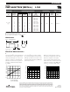
Electrical
Characteristics
Total Clearing I
2
t
The total clearing I
2
t at
rated voltage and at power
factor of 15% are given in
the electrical
characteristics. For other
voltages, the clearing I
2
t is
found by multiplying by
correction factor, K, given
as a function of applied working
voltage, E
g
, (rms).
Arc Voltage
T
his curve gives the peak
arc voltage, U
L
, which
may appear across the
fuse during its operation
as a function of theapplied
working voltage, E
g
, (rms)
at a power factor of 15%.
Power Losses
Watts loss at rated current
is given in the electrical
characteristics. The curve
allows the calculation of
the power losses at load
currents lower than the
rated current. The
correction factor, K
p
, is
given as a function of the
RMS load current, I
b
, in %
of the rated current.
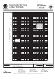
Catalog Numbers
Rated I
2
t (A
2
Sec)
Catalog Current Minimum Clearing At Watts
Numbers Size RMS-Amps Melting Rated Voltage Loss
Without Striker
FWP-1A14F 1— — —
FWP-2A14F 2— ——
FWP-2.5A14F 2.5 ———
FWP-3A14F 3— ——
FWP-4A14F 4— ——
FWP-5A14F 14 x 51mm 5 1.6 11.0 1.5
FWP-10A14F (
9
⁄1
6
" x 2") 10 3.6 38.5 4
FWP-15A14F 15 8.6 70 5.5
FWP-20A14F 20 26.0 230 6
FWP-25A14F 25 46.5 375 7
FWP-30A14F 30 58 485 9
FWP-32A14F 32 68 600 7.6
FWP-40A14F 40 84 750 8
FWP-50A14F 50 200 1800 9
With Striker*
FWP-10A14FI 10 3.6 38.5 4
FWP-15A14FI 15 8.6 70 5.5
FWP-20A14FI 14 x 51mm 20 26.0 230 6
FWP-25A14FI (
9
⁄16” x 2”) 25 46.5 375 7
FWP-30A14FI 30 58 485 9
FWP-32A14FI 32 68 600 7.6
FWP-40A14FI 40 84 750 8
FWP-50A14FI 50 200 1800 9
*Striker range is 600Vdc only
• Watts loss provided at rated current.
• See accessories on page 243.
Features and Benefits
• Excellent cycling capability and DC performance
• Low arc voltage and low energy let-through (
I2
t)
• Low watts loss in a compact size
• Used with finger-safe holders/blocks
U
L
1
.4
1.2
10
3
6
8
7
9
5
4
3
2
00 300 400 500 600 700
E
g
Kp
1.0
0.8
0.4
0.5
0.6
0.3
0.2
0.1
30 40 50 60
70
80 90 100%
I
b
K
1.4
1.2
1.0
0.6
0.8
0.7
0.9
0.5
0.4
0.3
200 300 400 500 600 700
E
g
1)
2)
1) 5-30A Range
2) 32-50A Range
50.8
(2.000")
15.5
(0.610")
14.3
(0.563")
With Striker
Without Striker
FWP with
striker option.
Electrical Characteristics
Data Sheet: 720025