
Use and Care Manual


3
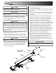
E. Connect the 2-pin connector on the power cable to the
control box mating connector.
F.
Connect wire harness single connectors to control box connectors.
G. Connect fuse connector to the fuse terminal or ignition switch
(5 AMP max).
H. Lay out a path for the power cable to the battery, use quick
ties to secure power cable. DO NOT CONNECT TO BATTERY AT
THIS TIME!
I. Lay out path for wire harness to the rear of the vehicle. Stay
clear of the exhaust system. Excess heat can damage the wire
harnesses. Use quick ties to secure harness to underbody.
J. Connect the wire harness to the motors and vibrator. Make
sure wire colors on wire harness match colors on the motor.
K. Thoroughly clean battery terminals. Make sure battery
terminals have no tarnish or corrosion. DO NOT CONNECT WIRE
HARNESS TO DAMAGED OR CORRODED TERMINALS! IT MAY
RESULT IN OVERHEATING, LOST POWER AND POTENTIAL
CONTROLLER DAMAGE! Install the circuit breaker within 12"
from the battery. Connect red wire from cable 3035935 and
battery cable 3001379 to circuit breaker according to the breaker
markings. Connect the power cable and battery cable directly to
the battery. Make sure connection to battery terminals is good
and tight. Loose connection to battery terminals will result in
sparking, overheating and possible battery damage!
L. Insure all functions of the controller are working properly.
M. Observe auger/ chain moving in proper direction. If direction
is wrong reverse wires between Motor and Wire Harness.
N. Optional spot light (5 AMP max) can be installed on spreader.
Use utility light kit part number 3018009. Remove cap from
single white wire. Connect light to this wire and the trucks frames
known ground (negative).
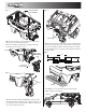
2. Control Box and Vehicle Wiring Harness Installation
Note: Make sure you have connected the proper wire color. This
is a wire ground electrical system! No Connections to truck’s
frame or body allowed!
Note: Always disconnect battery before attempting to install
electrical components on your vehicle
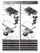
A. Mount the controller in a convenient location in the truck
cab. It is recommended not to mount the controller directly in
front of heat vents. Allow ample air space around controller
CAUTION
Inspect straps and hardware after each time spreader is loaded.
Tighten straps and hardware if necessary.
CAUTION
Do not mount controller in the way of air bag deployment!
WARNING
Important! Do not use ratchet straps or tailgate latch exclusively!
Always use spacer!
WARNING
Do not drill holes into fuel tanks, fuel lines, through electrical
wiring, etc that may be damaged by drilling. To insure good
performance of your spreader, check the condition of truck’s
electrical system. Using digital voltmeter, check alternator and
battery voltage. With engine running and head lights and heater
fan ON good voltage reading should fall between 13.0 and 15.3
volts. If voltage reading falls out of this range, check and adjust
your electric system.
IMPORTANT
Make sure all wires securely attached to vehicle or spreader. Use
wire ties and/or wire clamps to attach wires. All excess wires
must be rolled into bundles and attached to vehicle or spreader
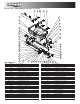
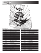
3016934
3030628
0203700
3035935
CB150PB
3001379
BATTERY POSITIVE
BATTERY NEGATIVE
CONNECT TO FUSE
OR WIRE IN FUSE PANEL,
CONTROLLED BY
IGNITION SWITCH
B.
Route both wire harnesses into truck cab through firewall (it
maybe necessary to drill holes). Insulate hole to avoid water leaks.
C. Insure no wires are nicked or damaged during installation.
D. Connect the 4-pin connector on the wire harness to the
control box 4-pin connector.