OWNER'S MANUAL MANUAL C & H A IR C O N D I T I O N E R S Air Conditioner CASSETTE SERIES MODELS: indoor unit outdoor unit GKH18K3BI GUHN18NK3AO GKH24K3BI GUHN24NK3AO GKH36K3BI GUHN36NM3AO GKH48K3BI GUHN48NM3AO Thanks for your selection of our Air-Conditioning Unit. Before use, please read this instruction manual carefully and keep it properly to ensure correct use of this machine.
1.
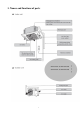
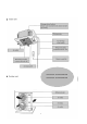
GKH36K3BI / GUHN36NMK3AO GKH48K3BI / GUHN48NMK3AO 2
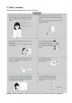
2. Safety cautions ●Read the following carefully to assure safe use. NOTE: Children should be supervised to ensure that they do not play with the appliance.
NOTE: This appliance is not intended for use by persons (including children) with reduced physical, sensory or mental capabilities, or lack of experience and knowledge, unless they have been given supervision or instruction concerning use of the appliance by a person responsible for their safety.
Safety Considerations Please read this manual carefully before use and operate correctly as instructed in the manual. 1 You are specially warned to note the two symbols below.: WARNING! A symbol indicating that improper operation might cause human death or severe injuries. A symbol indicating that improper operation might cause human injury or property damage. WARNING! ● ● This unit shall be used in the houses, offices, restaurants, residences or similar places.
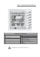
Wire controller (standard fitting) SWING SWING TIMER Composition of wire controller 9 1 Timing display 2 Fan speed display (Auto, High speed, Medium speed, Low speed) Failure st atus display 10 Sleep st atus display 11 Mode key 3 Defros ting st atus display 12 Se t temperatur e incr ease key 4 Ener gy saving st atus display 13 Se t temperatur e decr ease key 5 Se t temperatur e display 14 Fan speed key (fresh air setting) 6 Ambient temperatur e display 15 Sleep key (outdoor environmen
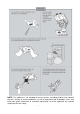
Operating instructions of wire controller Turning ON/OFF unit Press the ON/OFF key, then the unit shall start up. Press the ON/OFF key again, then the unit shall shut off. SWING TIMER Fan control (the figures show the relevant display areas) If the fan control key is pressed consecutively, the fan speed shall changes as per the following sequence: Low speed Medium speed High speed Auto In the dehumidifying mode: The fan speed shall be automatically set as low.
Swing function setting Press Swing button then the swing mode will be operated by the air conditioner. Repress Swing button once to stop swing mode. Note: There is no swing mode for duct type indoor unit SWING SWING TIMER Sleep function setting When under the cooling or dehumidifying mode, after receiving the SLEEP order for 1 hour, the previous set temp. Set will be risen for 1°C, and another 1°C will be risen after 2 hours that means that the temperature been risen 2°C within 2 hours.
Operating Mode Setting This key is pressed consecutively, the operating mode shall change as per the following sequence: SWING Cooling Dehumidifying Fan Heating Auto TIMER When the unit operates under “Cooling” mode, “COOL” shall be displayed. Now the set temperature must be lower than the ambient temperature. Now if the set temperature is higher than the ambient temperature, the unit shall not produce cooling effect but shall only operate under. Fan mode.
Timer Setting When the unit is shut off, timing start can be set; After the unit is started up, timing shutoff can be set. After the "TIMER" key is pressed, the unit enters the timing set status and the word "TIMER" flashes on the display. Now user can press ( ) or( ) key to increase or decrease the set time. Press the "TIMER" key again and then the timing shall go into effect. Now the unit starts to count the time passed.
Display outdoor temperature SWING Under normal conditions, the “OUT ENV” column shall only display the indoor temperature. Press the “SLEEP” key for 5 consecutive seconds when the unit is shut off or start up, the LCD shall display “OUT ENV”. After the outdoor temperature is displayed for 10 seconds, the system shall return to the display interface of indoor temperature. Note: If not equipped with an outdoor ambient sensor, the unit shall not have this function.
Failure Display SWING Fault code E0 E1 E2 E3 E4 E5 E6 When there is failure in the unit operation, “ERROR” will flash on the LCD of the wire controller and the code of failure will also be displayed. When there are multiple failures at the same time, the codes of failures will be displayed one after one on the wire controller. The first digit of the code denotes the system number. When there is only one system, it will display the system number 1. The last two digits denote the detailed failure code.
Unit Function • 7DP - Seven days programmer (Accessory not supplied) Centralized Control and Week Timer Functions: The centralized control- ler and the weekly timer are integra- ted in the same wire controller. The system has both the centralized control and the week timing functions. Up to 16 sets of units can be control- led simultaneously by the centralized controller (weekly timer). The weekly timer has the function of invalidating lower unit.
Note: 1. 2. For upper unit checks 16 lower units consecutively, there will be no more than 16 seconds delay when setting works till unit responds. Please let us know your requirement before your placing the order, for this WEEKLY TIMER will only be prepared when customer orders (communication joint with WEEKLY TIMER on manual control had been prepared). 1. Press or to select the unit that needed to be control.
Wire controller (with week timer functions) WARNING! ●Never install the wired controller where there is water leakage. ●Never knock, throw or frequently open the wired controller. Fig.
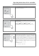
1) ON/OFF(Fig.2) Press the “ON/OFF” button, the unit will start running. Press the “ON/OFF” button again, the unit will stop running. Fig.2 2) Fan Control (Fig.3 is about display region and the same as following figures.) When press FAN button once, the fan speed will be changed as follow: In DRY mode: the fan speed will be set at low automatically. 3) Temperature Setting (Fig.4) Press the setting temperature button: Fig.
Setting temperature range under each mode: HEAT -------- 16℃~30℃ COOL -------- 16℃~30℃ DRY -------- 16℃~30℃ FAN -------- can not be set Auto mode is divides into new auto mode and old auto mode. NEW AUTO MODE --------------16℃~30℃ OLD AUTO MODE ---------- can not be set 4) Swing Setting (Fig.5) Press SWING button, SWING will be displayed on the LCD, in which case, the unit is under swing status. Press this button again, the words will disappear and the unit stops swinging.
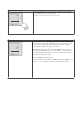
the outdoor unit will be frosted resulting in low efficiency of heating, in which case, the controller will automatically start to defrost with DEFROST displayed. Note: No heating for cooling-only unit and auto mode will be shielded after setting energy saving. 6) Timer Setting (Fig.7, 8, 9) Timer function in this wired controller connected with weekly timer is invalid and wired controller will be Fig.7 controlled by weekly timer.
In timing setting mode, press MODE button to select any desired setting object: Week (1-7), timer interval (1-4), timing (Timer on or Timer off time), min. part or hour part of time, and then press▲ or ▼ button to adjust this object, which is fixed by pressing TIMER button or can be canceled by pressing Timer again. During fixing setting there must be blinking characters. During canceling setting, if there are also blinking characters, setting can be continuous till quit It by Fig.
In deleting timing status, press ▲ or ▼ button to select one day of a week, and then press TIMER button to confirm, in which case, ”dd” is displayed .The day also can be canceled by pressing TIMER button without “dd” displayed. At last, press ON/OFF button to quit the setting after finish.(Fig.13) 7) Outdoor Ambient Temp Display ( Fig.14) In normal condition, only indoor ambient temp is Fig.13 displayed where “ENVIROMENT” is displayed.
blinking. Press▲ and ▼ to set lower-limit cooling temp (setting range is16-30) and then press ON/OFF to fix .Press ▲ and ▼ to set upper-limit cooling temp, which will be displayed where ambient temp is displayed (setting range is 16-30), and then press ON/OFF to fix. Note: Upper- limit temp can not be set to be lower than lowerlimit temp, or else the higher temp will be defaulted to be upper limit and the lower one to be lower- limit.
9) Power–off Memory Setting (Fig.16) Press mode button continuously for 10s and select if memorize startup and stop status of the unit or not at unit.01 displayed in the region of displaying setting temp indicates memorizing start and stop status of the unit after power off .02, quit by pressing ON/OFF button ,indicates not memorizing.
INSTRUCTIONS CHECKING ACT THE OPERATION INSTRUCTIONS CHECKINGBEFORE BEFORE RE CONT CONTACT CONTACT THESERVICE SERVICEMAN MAN OPERATION PROBLEM P ROBLEM CAUSES CA U S ES Check if breaker switch is still on
Indoor Unit Installation INSTALLATION A. Fig.1 Models GKH18K3BI H(mm) 230 GKH24K3BI 260 GKH36K3BI 320 GKH48K3BI B. Select install location of the indoor unit 1. Obstruct should put away from the intake or outlet vent of the indoor unit so that the airflow can be blown though all the room. 2. Make sure that the installation had accord with the requirement of the schematic diagram of installation spaces. 3.
6. Make sure that there are enough space for care and maintenance. Make sure that the weight between the indoor unit and ground is above 2300mm. 7. When installing the steeve bolt, check if the install place can stand the weight 4 times of the unit’s. If not, reinforce before installation. (Refer to the install cardboard and find where should be reinforced) The appliance shall not be installed in laundry.
☆ The drilling of holes in the ceiling must be done by the professional personnel. (160) Installation stands for main body of the unit Ceiling Above 20 Fig 1 Notes: The dimension for the ceiling openings with * marks can be as large as 910mm. But the overlapping sections of the ceiling and the decorated surface boards should be maintained at no less than 20mm. E.
☆ Please refer to the install cardboard about the dimension of ceiling opening. ☆ The central mark of the ceiling opening is marked on the install cardboard. ☆ Install the install cardboard on the unit by bolt (3 piece), and fix the angle of the drainage pipe at the outlet vent by bolt. 3. Adjust the unit to the suitable install place. 4. Check if the unit is horizontal. ☆ Inner drainage pump and bobber switch are included in the indoor unit, check if 4 angle of every unit are horizontal by water lever.
Note: 1. The standard pipe length is 5m,When the length(L) of the connecting pipe is less than or equals 5m,there is no need to add refrigerant. If the connecting pipe is longer than 5m,it is required to add refrigerant, in the above table, the amounts of refrigerant to be added for the models are listed for each additional meter of pipe length. 2. The pipe wall thickness shall be 0.5-1.0mm and the pipe wall shall be able to withstand the pressure of 6.0MPa. 3.
☆ Only use median sponge to entwine the wiring interface of the gas pipe and heat preservation sheath of the gas collection tube. G. Drainage hose 1. Install the drain hose ☆ The diameter of the drain hose should be equal or bigger than the connection pipe’s. ( The diameter of polythene pipe: Outer diameter 25mm Surface thickness ≥1.5mm) ☆ Drain hose should be short and drooping gradient should at less 1/100 to prevent the formation of air bubble.
Roof Drain raising hose . 220mm below500m m Drain hose . Hoisting stand below280m m 1-1.5m Within 300mm Clamp(attachment) Ceiling Drain hose(attachment) . should be within 75mm so that the drain hole doesn’t has to endure the unnecessary outside force. m below500m m ☆ The slant gradient of the attached drain hose below75m Instruction ☆ Please install the drain hose according to the following process if several drain hoses join together. T-tie in join drain hose .
Outdoor Unit Installation INSTALLATION INSTRUCTIONS Fig.31 Fig.
Outdoor Unit Installation INS TALLATION INS T R UC T IONS Electric wiring connection GUHN18NK3AO GUHN48NM3AO GUHN24NK3AO GUHN36NK3AO or CAUTION Wrong wiring ma y c a us e fire of electric s hock. D o not pull the wire when fixing it with wire clamp and clasp. Do not let the wire too loose All the electrical work must be done by qualified personnel according to the local rules and this instruction. T he rated voltage and the exclusive circuit must be used. Lea ka ge circuit-brea ker must be installed.
Profile Dimensions of Outdoor Unit Profile Dimensions of Outdoor Unit Fig. 30 Uni t mm Model GUHN36NM3AO GUHN18NK3AO GUHN24NK3AO A 848 1018 1018 950 B 320 412 412 C 540 700 840 412 1250 D 540 572 572 572 E 286 300 378 378 Item GUHN48NM3AO Fig.
Schematic Diagram of Unit Line Connection INSTALLATION INSTRUCTIONS Electric wiring connection The section area of cables selected by users must not be smaller than the specifications show diagram. The signal wire between indoor and outdoor unit shall be installed in the shielded bushing, and the unshielded twisted pair cable (UTP) shall be used, the cross sectional area of the cables must 2 be 0.75 mm .
Schematic Diagram of Unit Line Connection GUHN18NK3AO GUHN24NK3AO GUHN36NM3AO GUHN48NM3AO All the indoor units INSTALLATION INSTRUCTIONS
Position and Method of Installing Wire Controller Position and Method of Installing Wire Controller INSTALLATION INSTRUCTIONS INSTALLATION INSTRUCTIONS Position and Method of Installing Wire Controller 1. One end of the control wire of the manual controller is connected with main board of electric box of indoor unit inside, it should be tightened by wire clamp, the other end should be connected with the manual controller (installation sketch map as shown in below).
Position and Method of Installing Wire Controller Position and Method of Installing Wire Controller InstallationINSTALLATION instructions INSTRUCTIONS Electric box cover sketch map for indoor unit communication wire Wire clamp Control wire metallic Pipe Cable-cross loop Communication wire metallic Pipe 1 Figure 43 Surface Mounting of Cable Figure 44 Concealed mounting of Cable No.
Position and Method of Installing Wire Controller Position and Method of Installing Wire Controller Installation instructions INSTALLATION INSTRUCTIONS Caution: Before installing the electrical equipment, please pay attention to the following matters which have been specially pointed out by our designers: (1) Check to see if the power supply used conforms to the rated power supply specified on the nameplate. (2) The capacity of the power supply must be large enough.
PIPE PREPARATION OPERATION INSTRUCTIONS
REFRIGERANT PIPING WORK Item Size of Fitting Pipe (mm) Gas Pipe Model Liquid Pipe Max. Pipe Length (m) OPERATION INSTRUCTIONS Max.
AIR PURGING AND CHECK OF PIPE LEAKAGE OPERATION INSTRUCTIONS
LIQUID PIPE AND DRAIN PIPE OPERATION INSTRUCTIONS
ECK AFTER INSTALLATION Check after installation Items to be checked Possible malfunction Has it been fixed firmly? The unit may drop, shake or emit noise. Have you done the refrigerant leakage test? It may cause insufficient refrigerating capacity. Is heat insulation sufficient? It may cause condensation and dripping. Does the unit drain well? It may cause condensation and dripping.
This product must not be disposed together with the domestic waste. This product has to be disposed at an authorized place for recycling of electrical and electronic appliances.