MMAC-Plus™ 9F106-01 Two Port FDDI Router User’s Guide
Notice Notice Cabletron Systems reserves the right to make changes in specifications and other information contained in this document without prior notice. The reader should in all cases consult Cabletron Systems to determine whether any such changes have been made. The hardware, firmware, or software described in this manual is subject to change without notice.
Notice FCC Notice This device complies with Part 15 of the FCC rules. Operation is subject to the following two conditions: (1) this device may not cause harmful interference, and (2) this device must accept any interference received, including interference that may cause undesired operation. NOTE: This equipment has been tested and found to comply with the limits for a Class A digital device, pursuant to Part 15 of the FCC rules.
Notice DOC Notice This digital apparatus does not exceed the Class A limits for radio noise emissions from digital apparatus set out in the Radio Interference Regulations of the Canadian Department of Communications. Le présent appareil numérique n’émet pas de bruits radioélectriques dépassant les limites applicables aux appareils numériques de la class A prescrites dans le Règlement sur le brouillage radioélectrique édicté par le ministère des Communications du Canada.
Contents Chapter 1 Introduction Features........................................................................................................................... 1-1 Related Manuals............................................................................................................ 1-4 Getting Help .................................................................................................................. 1-4 Chapter 2 Installing the MMAC-Plus Module The Reset Switch .....................
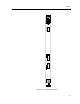
Chapter 1 Introduction The 9F106-01 module, shown in Figure 1-1, is a two port FDDI router. One front panel network connection can be made to this module and routed to any other MMAC-Plus module via the FNB bus. Features Processor The 9F106-01 is equipped with an advanced IDT R4600 Fourth Generation 64 bit RISC microprocessor. This microprocessor provides a platform for all management functions within a scalable RISC-based architecture.
Introduction Management Information Base (MIB) Support The 9F106-01 module provides MIB support including the following: • • NOTE IETF FDDI MIB IETF MIB II For a complete list of supported MIBs, refer to the release notes provided in the module package. LANVIEW LEDs The 9F106-01 uses LANVIEW: the Cabletron Systems built-in visual diagnostic and status monitoring system. With LANVIEW LEDs, you can quickly identify the device, port, and physical layer status at a glance.
Features FDDI 9F106-01 CPU SMB FNB 0 A U X C O N B FPIM 1 F D D I 0 A FPIM 1 MMAC PLUS Figure 1-1.
Introduction Related Manuals The manuals listed below should be used to supplement the procedures and technical data contained in this manual.
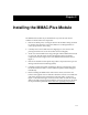
Chapter 2 Installing the MMAC-Plus Module The MMAC-Plus module may be installed into any of the 14 slots that are available. To install, follow the steps below: 1. Remove the blank panel, covering the slot that the module is being mounted in. All other slots must be covered, if modules are not being installed, to ensure proper airflow and cooling. 2. Carefully remove the module from the shipping box. (Save the box and packing materials in the event the module must be reshipped.) 3.
Installing the MMAC-Plus Module Plastic Tabs 7 FLNK 8 FLNK FLNK 10 RX FLNK INS TX 11 RX FLNK INS TX 12 RX Jack for ESD wrist strap Metal Back-Panel Circuit Card Card Guides Warning: Ensure that the circuit card is between the card guides. Lock down the top and bottom plastic tabs at the same time, applying even pressure. Figure 2-1.
The Reset Switch The Reset Switch The Reset switch is located on the front panel, under the top plastic tab, as shown in Figure 2-2. It serves two functions: • • Pressing the Reset switch twice within three seconds causes the processor to reset. Pressing and holding the switch on for three or more seconds causes the module to shutdown. Pressing and holding again for three seconds restarts the module. SNMP management may be used to disable this switch to enhance module security.
Installing the MMAC-Plus Module Table 2-1.
Local Management Console An RJ-45 connector provides a CON interface to the management terminal. Figure 2-3 shows the pinouts.
Installing the MMAC-Plus Module Installing an FPIM The 9F106-01 module is shipped without FPIMs. To install an FPIM, follow the procedure below: 1. Remove the module if it is installed in the MMAC-Plus chassis. 2. Remove the blank front cover over the FPIM slot. 3. Install the FPIM as shown in Figure 2-4. Ensure that the rear connector is seated firmly before tightening the two mounting screws. Figure 2-4.
Chapter 3 Operation The 9F106-01 FDDI module is a two port router for the MMAC-Plus. One front panel network connection can be made to this module and routed to any other MMAC-Plus module via the FNB bus. DC/DC Converter SMB-1 System Diagnostic Controller A DAS Interface CPU FNB-1 or FNB-2 B Front Panel CON Ports Figure 3-1.
Operation Flexible Network Bus (FNB) The FNB consists of two dual FDDI networks, the FNB-1 and FNB-2, providing up to 400 Mbps of data bandwidth. These FDDI networks are 100% ANSI FDDIcompliant, supporting SMT (version 7.3), MAC, PHY, and PMD standards. This allows the FNB to traverse multiple MMAC-Plus hubs, or connect to any ANSI FDDI-compliant device, through standard A/B port connections. System Management Buses The SMB-1 is a 1 Mbps management bus located within the MMAC-Plus.
FNB Interface FNB Interface MMAC-Plus modules are designed with one of two attachment policies. One allows dual attachment of a module to either FNB-1 or FNB-2; the second allows dual attachment to both FNB-1 and FNB-2. The 9F106-01 has one dual attachment to the FNB backplane, connecting to either FNB-1 or FNB-2. The module can insert into the FNB or bypass it.
Chapter 4 LANVIEW LEDs The front panel LANVIEW LEDs, shown in Figure 4-1, indicate the status of the module and may be used as an aid in troubleshooting. FDDI 9F106-01 System Status FNB Receive FDDI Transmit FDDI Receive SMB CPU FNB Transmit FNB A U X C O N Figure 4-1.
LANVIEW LEDs The functions of the System Management Bus (SMB) and CPU LEDs are listed in Table 4-1. Table 4-1. SMB and CPU LEDs State LED Color Description Green Functional Fully operational. Yellow (Flashing) Crippled Conditional FDDI fault *. Yellow Booting Booting. Red Reset Normal power-up reset. Red (Flashing) Failed FDDI Fault (FNB is down). Off Power off Module powered off. * Front Panel FDDI down. The function of the FNB Receive LED is listed in Table 4-2. Table 4-2.
LANVIEW LEDs The function of the FDDI Receive LED is listed in Table 4-4. Table 4-4. FDDI Receive LED State LED Color Yellow (Flashing) Activity (Flashing rate indicates rate of activity). Off No activity The Function of the FDDI Transmit LED is listed in Table 4-5. Table 4-5. FDDI Transmit LED State LED Color Green (Flashing) Activity (Flashing rate indicates rate of activity).
Chapter 5 Specifications Safety ! CAUTION It is the responsibility of the person who sells the system to which the module will be a part to ensure that the total system meets allowed limits of conducted and radiated emissions. This equipment meets the following safety requirements: • • • • • • • • UL 1950 CSA C22.2 No.
Specifications Physical Dimensions 35.0 D x 44.0 H x 3.0 W centimeters (13.8 D x 17.4 H x 1.2 W inches) Weight Unit: Shipping: 1.36 kg. (3 lb) 1.81 kg.
Appendix A FPIM Specifications This MMAC-Plus module uses Fiber Port Interface Modules (FPIM) to provide front panel cable connections. The FPIMs are user-installable. See the section titled Installing an FPIM on page 2-6. FPIM-00 The FPIM-00 has a MIC style connector supporting a multimode fiber connection. The specifications are listed in Table A-1. Table A-1. FPIM-00 Specifications Parameter Typical Value Worst Case Worst Case Budget Typical Budget Receive Sensitivity -30.5 dBm -28.
FPIM Specifications Transmitter power parameters are listed in Table A-2. Table A-2. Transmitter Power Parameters Parameter Typical Value Worst Case Worst Case Budget Typical Budget 50/125 µm fiber -13.0 dBm -15.0 dBm 13.0 dB 17.5 dB 62.5/125 µm fiber -10.0 dBm -12.0 dBm 16.0 dB 20.5 dB 100/140 µm fiber -7.0 dBm -9.0 dBm 19.0 dB 23.5 dB Error Rate Better than 10-10 The link distance is up to 2 kilometers on the multimode fiber-optic cable as specified by ANSI MMF-PMD.
FPIM-05 FPIM-05 The FPIM-05 has a MIC style connector supporting a Single-mode fiber connection. The specifications are listed in Table A-4. Table A-4. FPIM-05 Specifications Parameter Typical Minimum Maximum Transmitter Peak Wave Length 1300 nm 1270 nm 1330 nm Spectral Width 60 nm - 100 nm Rise Time 3.0 nsec 2.7 nsec 5.0 nsec Fall Time 2.5 nsec 2.2 nsec 5.0 nsec Duty Cycle 50.1% 49.6% 50.