
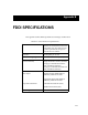
Specifications


B-3
FDDI DESIGN CONSIDERATIONS
Attenuation
Attenuation is the level of optical power loss measured in decibels (dB). The
maximum attenuation (attenuation budget) between any two active connections
to the ring, as defined by the FDDI standard, is 11 dB. The budget includes the
attenuation of the cabling, splices, connections, and optical bypass switches.
For example, the attenuation of the typical multimode fiber optic cable used in
FDDI networks is 2.5 dB/1km or 5 dB for the 2 km maximum node separation.
The attenuation of the typical optical bypass switch is 2.5 dB. With an 11 dB
budget to work with, and 5 dB expended on the cable, the maximum number of
bypass switches is two.
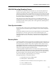
Number of Stations
The maximum number of devices in a single FDDI ring is 500. This limit is
determined by the propagation delay from 1000 physical connections. With the
exception of optical bypass switches, all FDDI devices are counted as two
connections against the 1000 physical connection budget. It is easy to see how
connections are counted when only dual attached stations are used (1000 divided
by 2 connections for each Dual Attachment Stations = 500 nodes), but to
understand how connections are counted for other device types, refer to
Figure 4-5. A Dual Attachment Concentrator without attached devices is counted
as two connections (main ring connections), the same as a Dual Attachment
Station. As each Single Attachment Station or Single Attachment Concentrator is
attached to the Dual Attachment Concentrator, two connections must be counted
against the budget, one for the concentrator port and one for the attached device.
This same logic applies to counting connections for a Single Attachment
Concentrator. The multiple ports of the concentrator are not counted until a
device is attached.