
User guide


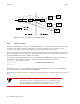
Table Of Contents
- SmartSwitch ATM Switch User Guide
- Table of Contents
- List of Figures
- List of Tables
- 1 Introduction
- 2 IP Over ATM and LANE
- 3 PNNI Routing
- 4 Routing
- 5 Virtual Ports and Static Connections
- 6 Traffic Management
- 7 Firmware Upgrades and Bootline Commands
- 8 ATM Filtering and Clocking
- 9 Troubleshooting
- Appendix A Agent Support
- Appendix B Technical Support
- Index

SmartSwitch ATM User Guide 3-7
PNNI Routing Multi-level PNNI Topology
Connectivity is now established between the two peer groups. For example, if LANE services are running on a switch
within peer group A, LANE clients can exist in group B. The clients in group B will traverse the link between the two
groups, find the LANE server in group A, and join the ELAN. Figure 3-2 shows a logical representation of the
topology created in the example.
Figure 3-2 Logical representation of connectivity between groups A and B
3.2.2 Physical Connections Between Peer Groups
Keep in mind that the two PGL switches (switches SWA3 and SWB3) do not have to be directly connected to each
other for the two peer groups to maintain connectivity. PGLs can find each other through any physical link that
connects the two groups. For example, if a second physical link is made between two other switches in groups A and
B (for instance, between SWA1 and SWB2), and if the physical link between the PGLs is removed, the PGLs will
reestablish their connectivity across the second physical link.
Adding Higher-level Peer Groups
Adapting the process in the example above, more sophisticated PNNI topologies can be created. For example, to
establish connectivity with other parent groups at level 72, do the following:
1. Make a physical connection between any two switches represented in the separate parent groups.
Peer Group A
Level 80
Peer Group B
Level 80
Level 72
Logical link
Physical Link
SWA1
SWA2
SWA3
SWB1
SWB2
SWB3
Logical Group Nodes
for Peer Groups A and B
SWA3
SWB3
Peer Group Leader Peer Group Leader
Parent Group of
Group A and B
Outside Uplink in show pnnilink command
N/A Horizontal Link to/from LGN in show pnnilink command