SEHI-22 AND SEHI-24 10BASE-T INTELLIGENT STACKABLE HUBS USER’S GUIDE CABLETRON SYSTEMS, P. O.
NOTICE Cabletron Systems reserves the right to make changes in specifications and other information contained in this document without prior notice. The reader should in all cases consult Cabletron Systems to determine whether any such changes have been made. The hardware, firmware, or software described in this manual is subject to change without notice.
NOTICE FCC NOTICE This device complies with Part 15 of the FCC rules. Operation is subject to the following two conditions: (1) this device may not cause harmful interference, and (2) this device must accept any interference received, including interference that may cause undesired operation. NOTE: This equipment has been tested and found to comply with the limits for a Class A digital device, pursuant to Part 15 of the FCC rules.
NOTICE CABLETRON SYSTEMS, INC. PROGRAM LICENSE AGREEMENT IMPORTANT: Before utilizing this product, carefully read this License Agreement. This document is an agreement between you, the end user, and Cabletron Systems, Inc. (“Cabletron”) that sets forth your rights and obligations with respect to the Cabletron software program (the “Program”) contained in this package. The Program may be contained in firmware, chips or other media.
NOTICE EXCLUSION OF WARRANTY AND DISCLAIMER OF LIABILITY 1. EXCLUSION OF WARRANTY. Except as may be specifically provided by Cabletron in writing, Cabletron makes no warranty, expressed or implied, concerning the Program (including its documentation and media).
TABLE OF CONTENTS CHAPTER 1 1.1 1.2 1.3 1.4 1.5 1.6 1.7 1.8 USING THIS MANUAL ............................................................................ 1-1 GETTING HELP ...................................................................................... 1-2 SEHI OVERVIEW .................................................................................... 1-3 SEHI FEATURES .................................................................................... 1-3 STACKABLE CAPABILITIES ...................
CONTENTS CHAPTER 5 5.1 5.2 5.3 5.4 INSTALLATION CHECK-OUT .................................................................5-1 USING LANVIEW ....................................................................................5-2 USING THE RESET BUTTON.................................................................5-4 SETTING THE NVRAM SWITCH ............................................................5-5 CHAPTER 6 6.1 6.2 6.3 EPIM INFORMATION EPIM SPECIFICATIONS .......................................
CHAPTER 1 INTRODUCTION Welcome to the Cabletron Systems SEHI-22 and SEHI-24 10BASE-T Intelligent Stackable Hub User’s Guide. This manual provides installation instructions and reference information for the SEHI-22 and SEHI-24.
CHAPTER 1: INTRODUCTION Chapter 1, Introduction, outlines the contents of this manual, briefly describes SEHI features, and concludes with a list of related manuals. Chapter 2, Installation Requirements/Specifications, describes installation requirements, network guidelines, and SEHI operating specifications. Chapter 3, Installation, contains instructions for installing the SEHI as a stackable or stand-alone hub.
SEHI OVERVIEW 1.3 SEHI OVERVIEW The 10BASE-T SEHI-22 and SEHI-24 are intelligent repeater hubs. The SEHI-22 has 12 RJ45 ports and one Ethernet Port Interface Module (EPIM) port on the front panel for network connections while the SEHI-24 has 24 RJ45 ports and two EPIM ports on the front panel for network connections. Both models have one rear panel HubSTACK Interconnect Bus port for stackable connections. The SEHI is designed to manage the Cabletron SEH series of non-intelligent stackable hubs. 1.
CHAPTER 1: INTRODUCTION LANVIEW LEDs Cabletron Systems LANVIEW Status Monitoring and Diagnostics System is a troubleshooting tool that helps in diagnosing power failures, collisions, cable faults, and link problems. The LANVIEW LEDs are conveniently located on the SEHI front panel. Reset Button Resetting the hub with the front panel Reset Button reboots the SEHI and initializes the processor. Local Management Manage the SEHI and its attached segments through Local Management on the SEHI.
REMOTE NETWORK MANAGEMENT CAPABILITIES 1.6 REMOTE NETWORK MANAGEMENT CAPABILITIES Manage the SEHI remotely with any SNMP network management system. Cabletron Systems offers the following remote management packages: 1.
CHAPTER 1: INTRODUCTION Table 1-2 lists the board revision requirements for EPIMs used in the SEHI-22/24. The board revision number is located on the EPIM’s printed circuit board directly after the part number as shown in Figure 1-2. Table 1-2.
RELATED MANUALS HubSTACK Interconnect Cables Stack hubs together with Cabletron HubSTACK Interconnect cables. Table 1-3 lists the part number and the application for each cable. Table 1-3. HubSTACK Interconnect Cables Part Number Description Application 9380110 12" HubSTACK Interconnect Cable SEH to SEH connections 9380111 18" HubSTACK Interconnect Cable SEHI to SEH connections Rack Mount Capabilities The SEHI can be installed in a 19-inch rack.
CHAPTER 2 INSTALLATION REQUIREMENTS/SPECIFICATIONS This Chapter describes cabling requirements, network guidelines, and operating specifications for the SEHI. The network must meet the requirements and conditions specified in this chapter to obtain satisfactory performance from this equipment. Failure to follow these guidelines could result in poor network performance. 2.
CHAPTER 2: INSTALLATION REQUIREMENTS/SPECIFICATIONS 2.1.2 UTP and STP Cable Specifications The device at the other end of the twisted pair segment must meet IEEE 802.3 10BASE-T specifications. When connecting a 10BASE-T Twisted Pair Segment to the SEHI 10BASE-T Twisted Pair Network Ports and EPIM-T module, the network must meet the following requirements: Length The IEEE 802.
CABLE SPECIFICATIONS Delay The maximum propagation delay of a 10BASE-T link segment must not exceed 1000 ns. This 1000 ns maximum delay limits the maximum link segment length to no greater than 200 meters. Crosstalk Crosstalk is caused by signal coupling between the different cable pairs contained within a multi-pair cable bundle. 10BASE-T transceivers are designed so that the user does not need to be concerned about cable crosstalk, provided the cable meets all other requirements.
CHAPTER 2: INSTALLATION REQUIREMENTS/SPECIFICATIONS 2.2 NETWORK PORT SPECIFICATIONS The SEHI-22 and SEHI-24 network ports use shielded RJ45 connectors that support STP and UTP cabling. Figure 2-1 shows the RJ45 pinouts. 12345678 1X 3X 5X 1. Receive + 2. Receive 3. Transmit + 4. Not Used 5. Not Used 6. Transmit 7. Not Used 8. Not Used 1490_3 Figure 2-1. RJ45 Network Ports 2.3 COM PORT REQUIREMENTS The RJ45 COM port supports access to a Local Management Console.
TRANSCEIVER REQUIREMENTS 2.4 TRANSCEIVER REQUIREMENTS When connecting an external network segment via a transceiver to the SEHI with an EPIM-A, the following requirements must be met: 2.5 • The transceiver or Ethernet Device to which the module will be connected must meet IEEE 802.3 standards, and/or Ethernet Version 1.0 or Version 2.0 standards. • The Signal Quality Error (SQE) test function on the transceiver must be disabled when it is connected to a repeater or to an Ethernet Version 1.0 device.
CHAPTER 2: INSTALLATION REQUIREMENTS/SPECIFICATIONS Delay Times (Start of Packets): Twisted Pair to EPIM-A 1.10 µs Twisted Pair to Twisted Pair 1.00 µs EPIM-A to Twisted Pair 1.00 µs Delay Times (JAM): Twisted Pair to EPIM-A 960 ns Preamble: Input: Minimum of 40 bits required Output: 64 bits minimum (last 2 bits are 1,1) JAM Output: Collisions are propagated through the network using the JAM signal of an alternating pattern of 1's and 0's in accordance with 802.
OPERATING SPECIFICATIONS Fault Protection: Each segment disconnects itself from the other segments if 32 consecutive collisions occur, or if the collision detector of a segment is on for longer than approximately 110 µs. This fault protection resets automatically after one packet is transmitted/received onto the fault protected segment without causing a collision. Power Supply Requirements NOTE The SEHI has a universal power supply.
CHAPTER 2: INSTALLATION REQUIREMENTS/SPECIFICATIONS Safety This unit meets the safety requirements of UL1950 (without D3 deviations), CSA C22.2 No. 950, and EN60950. EMI This unit meets the EMI requirements of FCC Part 15 Class A, EN55022 Class A and VCCI Class I. EMC This unit meets the EMC requirements of EN 50082-1 including: IEC 801-2 (ESD) levels 1 through 4, IEC 801-3 (Radiated Susceptibility) levels 1 through 4, and IEC 801-4 (EFT/B) levels 1 through 4.
CHAPTER 3 INSTALLATION This chapter outlines the procedure for attaching the SEHI to the network as a stackable or standalone device. Ensure that the network meets the guidelines and requirements outlined in Chapter 2, Installation Requirements/Specifications, before installing the SEHI. Failure to follow installation instructions may result in an electrical shock hazard. 3.1 UNPACKING THE SEHI Unpack the SEHI as follows: 1. Remove the shipping material covering the SEHI in the shipping box. 2.
CHAPTER 3: INSTALLATION 3.2 PRE-INSTALLATION CHECKOUT The SEHI is equipped with an NVRAM reset switch (Figure 3-1) located behind the grillwork on the side of the hub. Ensure that this switch is in the DOWN position by looking in through the grillwork on the right side of the hub. If the switch is UP, move it into the DOWN position with a non-metallic tool. Do not remove the chassis cover to perform this operation.
INSTALLING THE SEHI 3.3.1 Tabletop or Shelf Installation The following two subsections provide guidelines for installation on a tabletop or shelf. Guidelines for Tabletop and Shelf Installations Tabletop and shelf installations must be within reach of the network cabling and meet the requirements listed below: • • • A single phase 120 Vac, 15 A, grounded power receptacle must be located within seven feet of the location.
CHAPTER 3: INSTALLATION 3.3.2 Rackmount Installation Requirements To install the SEHI in a 19-inch rack, Cabletron Systems offers an accessory kit to install the SEHI in a 19-inch rack that includes rack mount brackets, mounting screws, and a strain-relief bracket for cable management. The accessory kit is not included with the SEHI, but is purchased separately from Cabletron Systems as part number SEHI-ACCY-KIT.
INSTALLING THE SEHI Rack Mounting Brackets (2) Strain Relief Bracket 1491_08 Figure 3-3. SEHI Rack Mount Hardware 3.3.3 Attaching the Strain Relief Bracket Attach the strain relief bracket to the front of the SEHI as follows: 1. Locate the strain relief bracket and four 8-32 x 3/8 inch screws from the accessory kit included with the SEHI. Do not use screws other than those included with the SEHI accessory kit. Use of longer screws may damage the unit or cause electrical shock. 2.
CHAPTER 3: INSTALLATION 3.3.4 Rackmounting the SEHI Refer to Figure 3-5 and proceed as follows to install the SEHI into a 19-inch rack. 1. Locate the four 8-32 x 1/4" screws and the two rackmount brackets in the SEHI-ACCY-KIT package. Do not remove the cover from the SEHI. 2. Using the four 8-32 x 1/4" screws provided in the SEHI-ACCY-KIT accessory kit, attach the rack mounting brackets to the bottom of the SEHI as shown in Figure 3-5.
INSTALLING THE SEHI 19-Inch Rack HubSTACK 10BASE-T HUB WITH LANVIEW® SEHI-24 Screws (4) 1490_9 Figure 3-6. Installing the SEHI in the Rack If the installation requires that the SEHI is to be stacked, proceed to Section 3.3.5. Otherwise, continue by connecting power as described in Section 3.4. 3.3.5 Stacking the SEHI The rear panel of the SEHI has an Interconnect Bus Out Port (male connector). Daisy chain units together using Cabletron Systems HubSTACK Interconnect cables.
CHAPTER 3: INSTALLATION To stack SEH non-intelligent hubs together: 1. Attach the SEH HubSTACK Interconnect cable to the “OUT” port on the rear panel of the SEH as shown in Figure 3-7. 2. Attach the other end of the SEH HubSTACK Interconnect cable to the “IN” port on the rear panel of the SEH next in the stack.
CONNECTING THE SEHI TO THE POWER SOURCE Disconnect SEH and SEHI Interconnect Cables at the "OUT" Port. HubSTACK 10BASE-T HUB WITH LANVIEW® SEH-24 OUT SEH INTERCONNECT IN HubSTACK 10BASE-T HUB WITH LANVIEW® SEH-24 OUT SEH INTERCONNECT IN HubSTACK 10BASE-T HUB WITH LANVIEW® SEHI-24 SEH INTERCONNECT OUT 1490_11 Figure 3-8. Disconnecting the HubSTACK Interconnect Cable Proceed to Section 3.4 to connect power. 3.4 CONNECTING THE SEHI TO THE POWER SOURCE NOTE The SEHI has a universal power supply.
CHAPTER 3: INSTALLATION 3.5 ADDING/REPLACING EPIMs This section contains procedures on how to add or replace an Ethernet Port Interface Module (EPIM) to upgrade or change the capabilities of your SEHI. After installing a new EPIM, refer to the appropriate EPIM section in Appendix A to verify proper operation. ! Observe all static precautions while handling EPIMs. CAUTION To install an EPIM: NOTE When removing an EPIM, pull the module straight out to prevent damage to the connector. 1.
CHAPTER 4 CONNECTING TO THE NETWORK This chapter outlines the procedure for connecting the SEHI to a network. Ensure that the network meets the guidelines and requirements outlined in Chapter 2, Installation Requirements/Specifications, before installing the SEHI. 4.1 CONNECTING THE SEHI TO THE NETWORK This section details the procedure for connecting network segments to the SEHI.
CHAPTER 4: CONNECTING TO THE NETWORK To connect the twisted pair segments to the SEHI: 1. Insert the RJ45 connector from each twisted pair segment into the desired network port on the SEHI. See Figure 4-1. EPIM-2 LNK EPIM-T 12X 10X 8X 6X 4X 2X LNK EPIM-T 11X 9X 7X 5X 3X 1X EPIM-1 1490_13 Figure 4-1. SEHI Network Ports 2. Check that the applicable LNK LED for the port is on. If the LED is off, perform each of the following steps until it is on: a.
CONNECTING THE SEHI TO THE NETWORK 4.1.2 Connecting a UTP Segment to an EPIM-T Before connecting a segment to the EPIM-T, check each end of the segment to determine if the wires have been crossed over for the proper connection. If the wires do not cross over, use the switch on the EPIM-T to internally cross over the RJ45 port. Refer to Figure 4-2 to properly set the EPIM-T crossover switch. Position X (crossed over) 1. RX+ 2. RX3. TX+ 4. NC 5. NC 6. TX7. NC 8. NC Position = (not crossed over) 1. TX+ 2.
CHAPTER 4: CONNECTING TO THE NETWORK d. Check that the twisted pair connection meets dB loss and cable specifications outlined in Chapter 2, Section 2.1.2. e. Check that the crossover switch is in the correct position. If a link is not established, contact Cabletron Systems Technical Support. 4.1.
CONNECTING THE SEHI TO THE NETWORK ! CAUTION Do not touch the ends of the fiber optic strands, and do not let the ends come in contact with dust, dirt, or other contaminants. Contamination of the ends causes problems in data transmissions. If the ends become contaminated, clean them with alcohol using a soft, clean, lint free cloth. To connect a fiber optic link segment to an EPIM-F1, EPIM-F2, or an EPIM-F3: 1.
CHAPTER 4: CONNECTING TO THE NETWORK F1/F2 ST Connectors F1/F2 SMA 906 Connectors w/ Half Alignment Sleeves SMA 905 Connectors F3 ST Connectors 1490_15 Figure 4-3.
CONNECTING THE SEHI TO THE NETWORK 4.1.4 Connecting a Thin-Net Segment to an EPIM-C To connect a thin-net segment to an EPIM-C: 1. Set the Internal Termination switch, located to the right of the port and labeled TERM to: • • The ON position ( ) if the thin-net segment connected directly to the port will be internally terminated at the port. • The OFF position (o) if the thin-net segment will not be internally terminated at the port or externally terminated. 2.
CHAPTER 4: CONNECTING TO THE NETWORK When internal termination switch is set to off ( ): Connect BNC tee-connector to port. Attach a terminator or terminated thin-net segment to one female connector of tee-connector. Connect a terminated thin-net segment to other female connector of tee-connector. Attach thin-net segment directly to BNC connector when internal termination switch is set to on ( ). 1490_16 Figure 4-4. The EPIM-C 4.1.
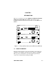
EPIM-A CONNECTING THE SEHI TO THE NETWORK 3. Connect the AUI cable to the AUI port located on the EPIM-A. See Figure 4-5. 4. Lock the AUI connector into place using the connector slide latch. EPIM-2 PWR EPIM-A 12X 10X 8X 6X 4X 2X PWR EPIM-A EPIM-1 11X 9X 7X 5X 3X 1X 1490_17 Figure 4-5. The EPIM-A 5. Check that the PWR LED on the EPIM-A is on. If the LED is not on, contact Cabletron Systems Technical Support. 6.
CHAPTER 4: CONNECTING TO THE NETWORK 4.1.6 Connecting an AUI Cable to an EPIM-X ! CAUTION The Signal Quality Error (SQE) switch remains in the OFF position for most network connections. However, some Data Terminal Equipment (DTE) requires SQE. Refer to a DTE manual for SQE requirement information. To connect an EPIM-X to a device not requiring SQE: 1. Check that the SQE LED on the EPIM-X is off. If the SQE LED is on, check the position of the SQE switch.
FINISHING THE INSTALLATION 4.2 FINISHING THE INSTALLATION The SEHI is now ready for operation. Before placing the network into service, test the installation thoroughly, making sure that all stations can be addressed and that the SEHI and all stations are indicating normal operation. Ensure that the networking software is configured properly to match the installed network. If there are any errors or abnormal operation, proceed to Chapter 5, Troubleshooting.
CHAPTER 5 TROUBLESHOOTING This chapter contains instructions for using LANVIEW LEDs to troubleshoot physical layer network problems. It also describes how to reset the SEHI and how to reset the NVRAM switch. 5.1 INSTALLATION CHECK-OUT After connecting the SEHI to the network, verify that packets pass between all Ethernet devices connected to the SEHI and any other devices connected to the network. If there is a problem with any of the attached devices, check the link as follows: 1.
CHAPTER 5: TROUBLESHOOTING 2. If the remote station is ready and the LNK LED is on, but no data passes through the port, one of two conditions may exist: • Network management has disabled the port. • The port is segmented either because the collision detector was on for more than 110 µs or the SEHI detected more than 32 consecutive collisions on the attached segment. The affected port remains segmented until a good packet is transmitted/received without collisions.
USING LANVIEW HubSTACK SEHI-24 10BASE-T HUB WITH LANVIEW® 24X 24 22 20 18 16 14 12 10 8 RESET COM PWR CPU CLN 6 4 2 RCV LNK RCV LNK E2 E1 23 21 19 17 15 13 11 9 7 5 3 1 23X LED Name LED Color Definition PWR (Power) Off Green (Solid) No power Power CPU (Central Processing Unit) Off Green (Flashing) Green (Blinking) Red (Solid) CPU in BOOT process CPU initializing CPU functioning CPU not functioning CLN (Collision) Red Collision RCV (Receive) Yellow (Flashing) Off SEHI is recei
CHAPTER 5: TROUBLESHOOTING CLN This red LED indicates that a collision has occurred on one of the ports. RCV When a yellow RCV LED flashes, it indicates that the SEHI is receiving data packets from the associated port segment. Each SEHI port has a corresponding RCV LED: • Network Ports: RCV LEDs 1-24 • EPIM-1: RCV LED E1 • EPIM-2: RCV LED E2 LNK When a green LNK LED is on, it indicates an established link between the associated port and the device at the other end of the segment.
SETTING THE NVRAM SWITCH 5.4 SETTING THE NVRAM SWITCH To prevent the possibility of electrical shock, do not remove the chassis cover to access the NVRAM switch, and use only a non-metallic tool when moving the NVRAM switch. The SEHI uses NVRAM (Non-Volatile Random Access Memory) to store user-entered parameters such as IP address and Community Names. To reset these parameters to the factory defaults, refer to Figure 5-2 and perform the following steps: 1.
CHAPTER 6 LOCAL MANAGEMENT This chapter explains how to set up a management terminal to access the SEHI Local Management. It also explains how to use the Local Management screens and commands. Local Management supplies the tools to manage the SEHI and all of its attached segments. It allows the user to: • Assign an IP address and subnet mask. • Select a default gateway. • Control access to the SEHI through the community names established in the Community Name Table.
CHAPTER 6: LOCAL MANAGEMENT 6.1 MANAGEMENT TERMINAL REQUIREMENTS Use one of the following systems to access Local Management: • A Digital Equipment Corporation VT series terminal • A VT type terminal running emulation programs for the Digital Equipment Corporation VT series • An IBM or compatible PC running a VT series emulation software package An RJ45 console cable is used to attach the management terminal to the SEHI.
MANAGEMENT TERMINAL REQUIREMENTS 2. Attach the female end (25-pin or 9-pin, as applicable) to the COM port on the terminal. HubSTACK 10BASE-T HUB WITH LANVIEW® SEHI-24 EPIM-1 COM COM RJ45 Port Console Cable EPIM-2 Management Terminal COM Port 1490_20 Figure 6-1. Management Terminal Connection 6.1.2 Management Terminal Setup Parameters Table 6-1 lists the setup parameters for the local management terminal.
CHAPTER 6: LOCAL MANAGEMENT Table 6-1.
ACCESSING LOCAL MANAGEMENT 6.2 ACCESSING LOCAL MANAGEMENT After configuring the local management terminal and properly attaching the cables to the SEHI, access the Local Management interface. To access Local Management: 1. Power up the terminal. The SEHI password screen (Figure 6-2) appears. SEHI LOCAL MANAGEMENT Cabletron SEHI Revision X.XX.XX Cabletron Systems Incorporated 35 Industrial Way, P.O. Box 5005 Rochester, NH 03867-0505 U.S.A. (603) 332-9400 (c) Copyright Cabletron Systems, Inc.
CHAPTER 6: LOCAL MANAGEMENT 3. Press the Return key. • If the password entry is invalid, the cursor returns to the beginning of the password entry field. • If the password is valid, the associated access privilege appears briefly, then the SEHI Local Management Feature Selection screen shown in Figure 6-3 appears. NOTE If the terminal keyboard is not used for 15 minutes, the Local Management session ends and the screen defaults to the Password screen.
USING THE LOCAL MANAGEMENT SCREENS 6.3 USING THE LOCAL MANAGEMENT SCREENS The Feature Selection screen is the main menu screen for SEHI Local Management. There are five screen options in the Feature Selection screen: Community Name Table, IP Address Assignment, Component Trap Table, SNMP Tool Support, and Device Statistics. Use the arrow keys to highlight an option, then press Return (or press the corresponding Function Key). The selected screen appears.
CHAPTER 6: LOCAL MANAGEMENT Community names are set through the Community Name Table option. Community names are passwords to Local Management and they are agents of security control to the SEHI. SEHI access is controlled by establishing up to four different levels of security authorization: Basic-Read, Read-Only, Read-Write, and Super-User. With Super-User access, the user changes the existing passwords by changing the community names.
USING THE LOCAL MANAGEMENT SCREENS Editing the Community Name Field The password used to access Local Management at the Password screen must have Super-User privileges for the edits to take effect. If a password is entered with Basic-Read, Read-Only, or Read-Write privileges, Local Management displays the message “AUTHORIZATION PROHIBITS ACCESS”, and does not include editing capabilities. To edit the Community Name field: 1.
CHAPTER 6: LOCAL MANAGEMENT 6.3.2 The Configuration Screen To access the Configuration screen from the Feature Selection screen, use the arrow keys to highlight the IP Address Assignment option, then press the Return key or F7. The Configuration screen shown in Figure 6-5 appears. SEHI LOCAL MANAGEMENT Cabletron SEHI Revision X.XX.XX CONFIGURATION I/F IP Address 1 000.000.000.000 SubNET Mask MAC Address 000.000.000.000 00-00-1d-05-dc- 36 Default Gateway: 0.0.0.
USING THE LOCAL MANAGEMENT SCREENS IP Address Displays the IP address of the SEHI. SubNet Mask Displays the subnet mask for the SEHI. A subnet mask is a 32-bit quantity which “masks out” the network bits of the IP address. This is done by setting the bits in the mask to 1 when the network treats the corresponding bits in the IP address as part of the network or subnetwork address, or to 0 if the corresponding bit identifies the host. MAC Address Displays the physical address associated with the interface.
CHAPTER 6: LOCAL MANAGEMENT Setting the IP Address To set the IP Address: 1. Use the arrow keys to highlight the IP Address field. 2. Enter the IP address into this field. The format for this entry is XXX.XXX.XXX.XXX, with values for XXX being from 0 to 255. The screen beeps if non-numerics or adjacent dots are entered. If the entry does not have three dots it will be rejected. 3. Press Return. The IP address appears and the natural subnet mask for the user is generated and also appears. 4.
USING THE LOCAL MANAGEMENT SCREENS To set the subnet mask: 1. Use the arrow keys to highlight the SubNET Mask field. 2. Enter the subnet mask into this field. The format for this entry is XXX.XXX.XXX.XXX with values for XXX being from 0 to 255. 3. Press the Return key. 4. Use the arrow keys to highlight the SAVE option, then press the Return key or F6. The “SAVED OK” message appears indicating that the changes have been saved to memory.
CHAPTER 6: LOCAL MANAGEMENT Using the Port ENABLE Override To set the Port ENABLE Override: 1. Use the arrow keys to highlight the Port ENABLE Override field. 2. Press the Return key to toggle from the default setting of “OVERRIDE DISABLED” to “OVERRIDE ENABLED”. 3. The adjacent field displays “Y/N”. Enter Y to continue enabling all of the ports, or N to discontinue the port enable override. If Y is entered, all existing ports are enabled, and the message “PORT ENABLED” appears.
USING THE LOCAL MANAGEMENT SCREENS 6.3.3 The Trap Table Screen Access the Trap Table screen from the Features Selection screen using the arrow keys to highlight the Component Trap Table option, then press the Return key or F8. The screen shown in Figure 6-6 appears. SEHI LOCAL MANAGEMENT Cabletron SEHI Revision X.XX.XX TRAP TABLE SNMP Community Name IP Address Traps N 0.0.0.0 N 0.0.0.0 N 0.0.0.0 N 0.0.0.0 N 0.0.0.0 N 0.0.0.0 N 0.0.0.0 N 0.
CHAPTER 6: LOCAL MANAGEMENT Configuring the Trap Table To configure the Trap Table: 1. Use the arrow keys to highlight the SNMP Community Name field, then enter the community name. 2. Press the Return key. 3. Use the arrow keys to highlight the Traps field and enter Y (or y) to send alarms from the SEHI to the workstation, or N (or n) to prevent alarms from being sent. 4. Press the Return key. 5. Use the arrow keys to highlight the appropriate Trap IP Address field. 6.
USING THE LOCAL MANAGEMENT SCREENS 6.3.4 The SNMP Tools Screen This section describes how to use the SNMP Tools screen to access Management Information Bases (MIBs). Access to screen options depends on the access status accorded to the user’s community name. This section describes Super-User management capabilities. SNMP Tools allows access to valuable MIB information.
CHAPTER 6: LOCAL MANAGEMENT The following sections describe SNMP Tools screen fields and instructions on how to change them. Community Name Identifies the community name used as a password to determine access level to the MIB component. OID Prepend Specifies the number prefix common to all Object Identifiers (OIDs) found in the MIBs - 1.3.6.1 is the default prefix OID. This is a modifiable field. Get Lets you retrieve MIB objects using SNMP protocol.
USING THE LOCAL MANAGEMENT SCREENS Step Displays the MIB walk, step by step, giving the user time to view specific leaves in detail. Cycles Allows the user to specify the number of get next requests to cycle through and how much time will elapse between each request. Repeat Repeats the last Get command, allowing the user to monitor changes to a specific OID. Getting Individual OIDs To get an OID: 1. Highlight GET, using the arrow keys, then press the Return key (or press the F6 function key).
CHAPTER 6: LOCAL MANAGEMENT Getting the Next OID To get the next OID: 1. Highlight GETNEXT by using the arrow keys, then press the Return key (or press the F8 function key). “ OID (=|F9)” appears. 2. Enter the desired OID, or OID extension. (Press F9 to recall the last OID request. The recalled OID may then be modified as necessary.) 3. Press the Return key.
USING THE LOCAL MANAGEMENT SCREENS Viewing Multiple OIDs Viewing several object identifiers at one time allows the user to quickly scan a MIB for the specific information that is needed. The Walk scrolls through OIDs numerically sequential to the initial OID request. The Step command scrolls the MIB Walk, one OID at a time. Cycling allows you to specify how many GetNext commands to cycle through for one OID. Walking Through OIDs To walk through an OID: 1.
CHAPTER 6: LOCAL MANAGEMENT Cycling Through OIDs To cycle through an OID: 1. Use the arrow keys to Highlight CYCLES, then press Return. 2. Enter the number of cycles desired to occur after “ENTER CYCLE COUNT:”, then press the Return key. 3. Enter how many seconds delay desired between get next requests after “ENTER CYCLE DELAY (secs):”, then press the Return key. Exiting the SNMP Tools Screen To exit the SNMP Tools Screen: 1. Use the arrow keys to highlight the RETURN command. 2. Press the Return key.
USING THE LOCAL MANAGEMENT SCREENS SEHI LOCAL MANAGEMENT Cabletron SEHI Revision X.XX.XX DEVICE STATISTICS STACK TOTAL BYTES RECEIVED: FRAMES RECEIVED: 3792125 16547 ERRORS RECEIVED: COLLISIONS: OOW COLLISIONS: CRC ERRORS: ALIGNMENT ERRORS: RUNT PACKETS: GIANT PACKETS: PORT ADMIN. STATUS: PORT SEG.
CHAPTER 6: LOCAL MANAGEMENT OOW Collisions Displays the number of Out Of Window collisions. OOW collisions are usually caused by the network being too long where the round trip propagation delay is greater than 51.2 µs (the collision domain is too large), a station somewhere on the network is violating Carrier Sense and transmitting at will, or a cable somewhere on the network failed during the transmission of the packet.
USING THE LOCAL MANAGEMENT SCREENS Disable Port This command lets the user Disable the selected port. Update-Freq This command lets the user select the time interval between Stack/Module/Port counter updates. Choose update intervals in increments of 3 seconds, with the maximum interval being 99 seconds. Module This command lets the user view statistics for a selected module in the stack. The SEHI is Module 1 and each SEH in the stack follows in sequential order.
CHAPTER 6: LOCAL MANAGEMENT Selecting the Appropriate Module/Port When the Device Statistics screen first appears, statistics are displayed for Module 1 and Port 1. To view statistics for another module and port, use the Module x or Port x commands at the bottom of the screen. To select a module or port: 1. Use the arrow keys to highlight the Module or Port command. 2. Press the shift and + keys, or the - key until the desired module or port number appears. 3. Press the Return key.
USING THE LOCAL MANAGEMENT SCREENS Using the Disable Port Command The Disable Port command lets the user disable the port selected in the Port command. The user must first use the Port command to select the desired port. To set the Port Disable command: 1. Use the arrow keys to highlight the Disable Port command at the bottom of the screen. 2. Press the Return key. The corresponding port is enabled and the Port Admin Status field is updated.
APPENDIX A EPIM INFORMATION A.1 EPIM SPECIFICATIONS EPIMs enable the connection of the SEHI to the main network using different media types. Cabletron Systems offers a variety of EPIMs. The following sections explain specifications for each EPIM. A.1.1 EPIM-T The EPIM-T is an RJ45 connector supporting UTP cabling. It has an internal Cabletron Systems TPT-T 10BASE-T Twisted Pair Transceiver. The slide switch on the EPIM-T determines the cross-over status of the cable pairs.
APPENDIX A: EPIM INFORMATION A.1.2 EPIM-F1 and EPIM-F2 The EPIM-F1 and EPIM-F2 shown in Figure A-2 support Multimode Fiber Optic cabling. Each EPIM has an internal Cabletron Systems FOT-F Fiber Optic Transceiver. The EPIM-F1 is equipped with SMA Connectors and the EPIM-F2 is equipped with ST Connectors. Specifications for the EPIMs are listed below. 1490_31 1490_30 Figure A-2. EPIM-F1 and EPIM-F2 Value Worst Case Worst Case Budget Typical Budget Receive Sensitivity -30.5 dBm -28.
EPIM SPECIFICATIONS A.1.3 EPIM-F3 The EPIM-F3 shown in Figure A-3 supports Single Mode Fiber Optic cabling. It has an internal Cabletron Systems FOT-F Fiber Optic Transceiver and is equipped with ST Connectors. Specifications for the EPIM-F3 are listed below. 1490_32 Figure A-3. EPIM-F3 Note: Transmitter Power decreases as temperatures rise and increases as temperatures fall. Use the Output Power Coefficient to calculate increased or decreased power output for the operating environment.
APPENDIX A: EPIM INFORMATION Maximum Sensitivity (-36.0) Receive Sensitivity Typical Sensitivity (-31.0) Minimum Sensitivity (-30.0) Minimum Receive Input (-9.72) Typical Receive Input (-7.5) Maximum Receive Input Power Maximum Receive Input (-6.99) Maximum Transmit Power (-12.0) Transmitter Power* (At 25°C into 8.3/125µm fiber) Typical Transmit Power (-15.5) Minimum Transmit Power (-21.
EPIM SPECIFICATIONS A.1.4 EPIM-C The EPIM-C supports thin-net coaxial cabling and is equipped with an internal Cabletron Systems TMS-3 Transceiver. Use the TERM switch on the front of the EPIM-C to set the internal 50 Ohm terminator. This eliminates the need to connect the port to a tee-connector and terminator. Figure A-4 shows the setting for the terminator switch. TERM EPIM-C Internal Termination Switch = On (internally terminated) = Off (need external termination) 1490_34 Figure A-4.
APPENDIX A: EPIM INFORMATION A.1.5 EPIM-A and EPIM-X (AUI Port) The EPIM-A is a DB15 female connector used to attach segments to an external transceiver. The EPIM-X is equipped with dual internal transceivers. It has a DB15 male connector used to attach segments to an AUI cable. Figure A-5 shows both modules. 1490_35 Figure A-5. The EPIM-A and EPIM-X DB15 Pinouts Pin 1 2 3 4 5 6 7 Logic Ref. Collision + Transmit + Logic Ref.
APPENDIX B IMAGE FILE DOWNLOAD USING OIDs This appendix provides instructions for setting up a tftp server and to download an image file to the SEHI by setting specific MIB OID strings. Set the OID strings with the SNMP Tools screen described in Chapter 6. NOTE You can also download an image file using various remote packages such as Cabletron’s Remote LANVIEW/Windows. Refer to specific package documentation for image file download procedures. The SEHI supports the Standard Local Download application.
APPENDIX B: IMAGE FILE DOWNLOAD USING OIDs ! CAUTION If unsure about how to properly configure your UNIX workstation using these guidelines, contact your System Administrator. Note: For convenience, Cabletron includes the PKUNZIP utility for easy decompression of the “zipped” file.
STANDARD LOCAL DOWNLOAD 2. If you do NOT have a /tftpboot directory, then create one (e.g., unix% mkdir tftpboot). 3. Ensure that the /tftpboot directory is not owned (e.g., unix% chown nobody tftpboot). 4. Store the hex image file in the /tftpboot directory as sehi.hex. NOTE This step requires decompression of the zipped image file. If you do not have a UNIX unzip utility, access to a PC with pkunzip, or a way to FTP the decompressed image to your UNIX workstation, contact Cabletron Technical Support.
APPENDIX B: IMAGE FILE DOWNLOAD USING OIDs When performing the steps in table 1, keep the following in mind: • • • You must follow the steps in order. Enter the IP address of the tftp server in standard dotted decimal notation (e.g., 132.177.118.24). Enter the FULL path to the image file in the ctDLTFTPRequest OID, including the name of the image file (e.g., c:\tftpboot\sehi.hex). Table B-1. OIDs and Settings Step OID Name OID Number Data Type SNMP OID Data 1. ctDLForceOnBoot 1.3.6.1.4.1.52.4.1.5.
INDEX Numerics 10BASE-T cable length 2-2 crosstalk 2-3 delay 2-3 impedance 2-2 insertion loss 2-2 jitter 2-2 noise 2-3 temperature 2-3 UTP and STP specifications 2-2 A AUI Cable 4-8, 4-10 C Cable Specifications 2-1 UTP and STP 2-2 Cables HubSTACK Interconnect 1-7 Com Port 2-4 D Daughter Board 1-7 Default Gateway 6-13 Device Statistics Screen 6-22 Dimensions 2-8 E EMC Requirements 2-8 EMI Requirements 2-8 Environmental Requirements 2-7 EPIM Installation 3-10 EPIM Specifications 1-5 EPIM-A and EPIM-X A-6
INDEX N S Network Connection 4-1 AUI 4-8, 4-10 EPIM-A 4-8 EPIM-C 4-7 EPIM-F1/F2/F3 4-4 EPIM-T 4-3 EPIM-X 4-10 Fiber Optic Segment 4-4 SEHI-22/24 4-1 Thin-Net 4-7 Unshielded Twisted Pair 4-3 Network Port Specifications SEHI-22/24 2-4 NVRAM pre-installation checkout 3-2 setting 5-5 Safety Requirements 2-8 SEHI Features 1-3 Size dimensions 2-8 SNMP Tools Screen 6-17 Subnet Mask 6-12 T Technical Support 1-2 Transceiver Requirements 2-5 Trap Table Screen 6-15 Troubleshooting 5-1 O OIDs 6-17 Operating Speci
POWER SUPPLY CORD The mains cord used with this equipment must be a 2 conductor plus ground type with minimum 0.75 mm square conductors and must incorporate a standard IEC appliance coupler on one end and a mains plug on the other end which is suitable for the use and application of the product and that is approved for use in the country of application. GERMAN: Die Netzleitung, die mit diesem Geraet benuetzt wird, soll einen zwei Leiter mit Erdleiter haben, wobei die Leiter mindestens 0.