
Instruction manual


7
Electrical Connection
1. Open all electrical disconnects and install lock--out tag
before beginning any installation or service work.
2. All electrical connections, wire sizes and type of conduit
shall meet the National Electric Code and State and Local
Codes. Main power supply, minimum wire sizes, circuits,
fusing, etc. are shown on schematic wiring diagrams.
NOTE: Use minimum 75°C copper wire only.
3. Refer to base unit instructions for recommended wiring
procedures.
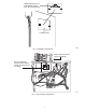
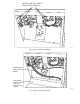
4. Connect low voltage wires as shown in unit schematic
diagrams. These connections must be made in the 24--v.
splice box (See Fig. 7).
5. Connect field power wiring as shown in unit wiring
diagram. All connections should be made inside the unit
and comply with the National Electric Code and State and
Local Codes. Heaters with factory installed circuit breakers
may be installed on a branch circuit protected by either a
fuse or circuit breaker. For all other heaters, the branch
circuit must be protected by a fuse or circuit breaker
supplied by others.
6. Make all high voltage wire splice connections inside the
unit control box. Use splice connectors provided. Properly
insulate connectors. Separate all wires from incoming
power leads (See Fig. 7).
7. Be sure that all electrical terminal connections, clamps,
screws, etc. are tight before proceeding.
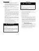
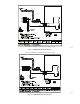
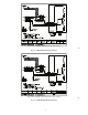
8. Check wiring diagram supplied with heater for specific
connections and information (See Fig. 9 thru 16).
9. Check operation as described in Start--Up section.
ELECTRICAL SHOCK HAZARD
Failure to follow this warning could result in personal
injury or death.
Before performing installation, service or maintenance
operations on this system, turn off all main power to system.
There may be more than one disconnect switch. Turn off
accessory heater power switch if applicable. Lock out and
tag switch with a suitable warning label.
!
WARNING
START --UP
ELECTRICAL SHOCK HAZARD
Failure to follow this caution may result in personal injury
or death.
Before proceeding, verify that all wiring is correct per
factory approved schematic. Notify equipment supplier
immediately of any discrepancies.
!
CAUTION
1. Refer to base unit installation instructions as required.
2. Check for loose terminal connections.
3. Check that all fuse and circuit breaker short circuit
interrupting ratings are adequate.
4. Turn on unit and heater power.
5. Set thermostat to call for heat.
6. Check operation of heater.
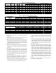
7. Check that airflow across the heater is at or above the
minimum recommended CFM requirement (See Table 2).
8. Use of accessory electric heaters that are not tested and
approved by the original equipment manufacturer of the
packaged air conditioner or heat pump is not recommended
and will not be warranted by the original equipment manu-
facturer. Additionally, damage caused by such heaters to the
equipment will not be covered under warranty by the
original equipment manufacturer.
TROUBLESHOOTING
1. Circuit Breakers--Malfunction will interrupt power to the
unit. Check for cause of failure, reset or replace.
2. Limit Switch--Malfunction prevents heating element(s) from
being energized. Replace switch if malfunction occurs.
3. Relay--Malfunction will not allow heater to ener gize.
Replace faulty relay . Do not attempt to repair.