DTPARTTETI pfrlnrcruumuir i,].: U'IPARIHTII. ,ffCilllGAL0RDER TMililz$5 . T0il6q30"GRR ' t RADIO i :; SET ,,.-i?jD. 'l'. F. e. AI\{IGRR-5 I!. E r;' t p*, I ".fi É iit , i f 4 i{.' . " ' tt 3' .W D E P A R T M E T Y T S ' OTPH E A R M Y A N D T H E A I R F O R C E AUGASTP52 .
TII 11-29J1 1'O 1(t-30-ClilÌ.
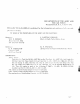
DEPARTMENTS OF THE ARMY AND THE AIR FORCE WlsnINcroN 25. D. C.. 8 Arrctttst1952 TM 11-295/TO16-30-cRR5-5is publishedfor the information and guiclzrtrce of all ('onr'(,1'ne(i. I A G ' 1 1 : ] . . 1("f 1t J u l 5 2 ) l Bv oRnonoF THESrcnprlnms oF THEARMY AND THE AIn Foncn: OrRrcrrr,: \V}T. F]. BERGIN IIa.ior General,USA lÌ'lre Ad.iutatttGeneral, J. LAWTON COLLINS Chief of Staff, Uníted SfafesArmy OF F IctIAL : N. F. T\YINING Actittg Chief ol Stalî, UtútedStafu,sAir I-ot'ce K. F].
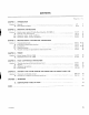
CONTENTS Paragraph C H A P T E Rt . Section I. n. C H A P T E R2 . Section L IL II1. W. C H A P T E R3 . Sectiott L II, III, rv. v. s Pao, INTRODUCTION General Description and data 1 ' 3-10 O P E R A T I N GI N S T R U C T I O N S Service upon receipt of Radio Receiving Set AN/GRR-5 Contlols and instruments Operation under usual conditions Operationunder unusual conditions.
WARNING FIIGH VOLTAGE is usedin the operation of this equipment. DEATH ON CONTACT may result if personnelfail to observesafety precautions.
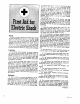
rs nc-c?sseDfcr selrty If lhe new locatlon ls more lhan. a fe* f611 .8.) r:1:dcjal resplrailonb e g i v e n w t r i t c r h e r : c r . j : . u u e i n g ' _ o r J . at oulO ii tnu method of tnnrport.Uon prohJblts the use of the ShaefÍer prone prìettur rncùod. other meihods of resU-Ecltauonmay bc urcd fìtÚure may be uiuatuO on the lront of the vlcrtm'r dlrpàragm, ó. tf,u Oìr".r mouth.tomouth method rîày b. u!€d. Arilndal res. plratlo_n,onc? started, nust be ""tinrJ, *-ìinout loss of rhythm. b.
a. (oRnÍcT PoslOpootot' t cllnu t î IO\'. l'rc.tnít^t dîd lxled. hn.d atd! tin't lo.. lrca l'.nl.lóot ond rcrli^g É. lonw.tN) slt l\'(i ^N D ?OSIT IONì i(; OF Liille jnstr lll.\rs. c.I)OWN$'.4nI)PnLSlltÍlE, o. .ítilt and rhicùt Rt:sî I'ostî toN. (l yralot rclcatct prcrttc *ùlorlg, rciny kck on hcdq aad ntu lot 2 sec.ondsfor a complete cycle.
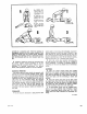
T r úa s s - r Fi,gure 1. Radì,oReceiuitzg Set AN IGRR-í.
CHAPTERI INTRODUCTION S e ction l. G E N E R A L l. Scope This manual contains instructions for the installation, operation,maintenance,ancl repair of Radio Receiving Set AN/GRR-5 (fig. 1). In addition to these instructions, there are t\.\'o appendixescovering a list of referencesand an identification table of narts. 2. Forms ond R.ecords The following forms l'ill be used for reporting unsatisfactory conciitionsof Army eqriipment. o.
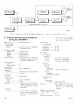
R A O I OR E O E I V I N G SET AN/GRR.5 CHEST SET GROUPAI'I/GSA-6 s4l]ol\|-sll'_av! rc-r_ _ _ _r i[E xgoMrygry.! T f, e95-3 FigtLre2. RadioReceiuingSetANlGRR-S,tgpicalsystent.cLppl,icatíott,sintpliftecî.blocl;diogt'tr of RodioRe5. TechnicolChorocteristics ceiving Set AN/GRR-5 Receivertype,- --.,, Superheterodyne. Types of signals which can be --.'--.A-m, c-w, or m-c-w (modulated received continuous wave). Frequency range: Band 1-- - - - - - . 1 , 5 m c t o 2 . 7m c . 2.7 mc to 5 mc.
6 . P o c k o g i n gD o t o a' \\'hen llackagecl for export shipment, the components of Raclio Rec-eivinr Set A\ GRR-5 are p l a c e d i t r r i ' a t e r l l r o o f c o n t a i n e r s a n d a r e p a c k e d i n a w o o d e n e x p o r t c r i i t e . T r ' p i t - r r ìp i r c k i i g i l g is i l l t t s t l a t e d i n f i . q u r e S .T h e s i z e , w e i g h t , a n c l v o l u m e o f t h e c r a t e a r e i n c l i c a t e r l i n t h e ,, lt l' .r r i , i r r r . c h l r r t : -\-r'l'.
lNTER/OR PACK I I REMOVE THREE ù rEEL R E M O V EW A T E R P R O OBFA G A N D L I F T I N T E R I O RP A C K F R O M M A S T E RC A R T O N R E M O V EN A I L S , U S I N GN A I L P U L L E R , R E M O V ET O q A N D L I F T OUT WATERPROOF CARTON 5 |XA|'S UÍAUL E CAUTION /LSTRUCTIONBOOKLOCATEDAT LOWER FOPT/ANOF RlGHT slDE FILLER -4 L : F To u r s p a R E p A R T s A N DA C C E S S O R I E S CARTON /? {,a? ;)7. ' 'ta' MASTER CARTON INSTRUCT/ON BOOK F/LLER 6 ne,.
Required C. --- i-.: No. <,: . \ ' f : , - :> . ' : : ] f S - l l r ^{ I - ì l : , : :t \ \ ' - l i L' P, :r':.1l-:.ì .. -\-.st-nrbll' I I Ileieht rin.r I I Len gth lln.I Depth (in.1 linit | 39l,b \3r/+ 96 11 57/z Volume (cu ft) (-'\-:: .-. t . t ' ': i ì - . . . \ : s e t . n b l y P, '.',-'.1 t^\ t:ti:, L-. ':rì,le P , , ' . .'. r ' ( -\-.sembly .20 t.) 1 1,5 tl4 C \ 1 : l ' ì ( )U . Htl,ìset Cold CX-1334/U Ilecti r-t r'-Porver supply conlt,cting cable.
ious controls for correct operation of the power supply, and in addition, the loudspeaker for the receiver. The various controls include the power-selector switch, power on-off switch, and speaker on-off switch. d. Mi,nor Componentsof Radío Receiuing Set AN/GRR-í (fiC.4). Included among the minor componentsof Radio Receiving Set AN/GRR-5 are the headset, headset cord, mast sections, and cable assemblies. See appendix II for complete descriptions. 2 Mast SectionsMS-116-A. 1 Mast SectionMS-l17-A.
1 0 . Ad d i t i o no l E q u i p me n tR e q u i red o. Tht fi'll(,\\'illgpo\yer sourcesare not suppìietlirs l)rit'trrf RndioReceivingSet AN/GRR-5 ìrut itre rctluireclfor its installationand operatiot-t: (1) 115 r'olts ac, 50 or 60 cps (cyclesper second) for fixed installation. (2) 6-volt, 12-volt, or 24-volt d-c storage battery for vehicular installation. (3) Two 90-volt batteries in parallel (Ba and bias supply) and one l.5-volt battery (filament supply) for field installation.
CHAPTER2 OPERATING INSTRUCTIONS sectionl. sERvlcEuPoN REcEtPT oF RADto REcEIvtNG sETAN/GRR-5 I l. Siting a. Erternul Requirentents, The location for radio equipment dependson the tactical situation and local conditions. Depressions,valleys, and other lorv places generally are poor locations for radio reception becausethe surrounding terrain absorbs r-f energy. Weak or Ltndesirable signals may be expectedif the set is operateclunder or closeto steeì bridges, Llnderpasses, power lines" or power units.
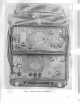
REFERENCE REAR F I L A M E N TV O L T A G E VIBRATOR B+ VOLTAGE REGULATOR @9 9@@qF oAu I INPUr / v'BRAroRl A 71 | I Tlol ll I \ c,,a ( H!..1,",?:r.. )l;.11ru,,# cK looT c c 6AG7 \-/ c c c FRONT TM295-tl Figut'e 5. Pou.er Sttpltly PP-J0SlURR, tttbe lctcntiott. REAR LLATOR IST I-F AMPLIFIER tL4 CONVERTER tR5 2D R-F AMPLIFIER tL4 A-F AMPLIFIER 3V4 I ST R-F AMPLIFIER tL4 20 I.F AMPLIFIER C A L I B R A T I O NO S C I L L A T O R c R -2 l U tR5 D E T E C T OA RV C .
;'. Í-i, lrl I rtstallatiott.If the equipmentis to be expr.,secl to the weather, keep the radio set in ('over ('\\'-211lU. In very hot weather, the cover should be removed to provide proper ventilation. c. Fired-Field lttstullatíon.
Cuutiott: \\-hen unpacking, keep sand and mucl flcim the ends of the mast sections. a. F iald Irtstullations. (1) Insert Mast Section MS_112_A into internal threaded portion of Mast Sec_ tion MS-118-A, and tighten. Insert Mast Section MS-116-A into internal threaded portion of Mast Section MS_ 117-4, and tighten. Insert Mast Sec_ tion MS-11G-A into another Mast Sec_ tion MS-116-A, and tighten. Insert Mast Section MS-116-.
auclconnectthe lug on the nrini,i ,'1 1]1.,sr)ul'ce, terminal of the shit'ld to the ttegtrtive (-) s0tìf ce. c. Dt'y-Battery Oyteratiott. Connect Polver Caìrle Assembly CX-1360/U to DRY BATTERY receptacleJ104, and secltrethe connector in place. Connect Battery BA-405iU to the plug on the cable nearest to the power supply chassis, and then connect tu'o Batteries BA419/IJ to the outer sockets on the calcle. Secure batteries in Bag CW-2I2,/U' Nofc. The initial ad.
I ffi;un*ffT:;:x::ggffi î W m ,WW b,ii**= "*=--u*i ft# lll,, ",i''; * #:''"'-:s qi ;3 ,àt TÀ-É '.:r, "!'] Figttre 9. Electron'ícEqzr.ipmentCabinet CY-615lURR, receit:eranclporcer supply rentot,ecl. 17. S e r v i c eu po n R e ce i p to f U se d o r R e c o n d i ti o n eE d q u i p me n t changes in this manual, plef eliiblr' on the schematic diagram. a. Follolv the instrr,rctionsin paragraph 12 for uncrating, unpacking, and checking new equipment. Ò.
A È { T Eh i T $ A r . e sér S r c T t * h J it'JprJr ! * w s+ ffi3 Figure 10. RcLòlioReceioer R-174lURR, rear oblique ,uiew. T Wg * s * t 3 f r'r s ,.fiúf Figtn"e 77, Power Supply PP-30SlURR,,rear obliqztet,i.eru. l4 T M 3S5- t4:.
S e c t i o nl l . C O N T R O L SA N D I N S T R U M E N T S 18 . R o d i o R e ce i ve R r -1 7 4 l U R R (figs. 10, 12, and 40) The follorving table lists the controls of the receiverand indicatestheir functions: Control Terminals A and G Control PHONES jacks (J2 andJ3). MONITORING INPLTT receptacle (J1). l'u n ct ion Pi'ovicler.neanscf connecting reel anf,enna. Antenna itrput i'ecep- P r o v i d e s m e a n s o f c o n n e c t i n g a n tacle (on top left tenna mast seetions. side). R.F.
DETENTFREQUENCY CHART F I N E T U N I N GK N O B I{UMBEREDDETENTS M A N U A LP - RESET T U N I N GK N O B C A N 4A R M LOCKING K E YA S S E M B L Y TM 295-5 Figure 12. RadioReceiterR-l74lLiRR, f rotztpanel T M2 9 5 - 6 Figttre 73. Porcer SuppIA PP-308IURR, f ront panel.
s e c t i o nl l l . O P E R A T | oU NN D E Ru s u A L c o N D t r t o N s Cuutíon: Reception on the loudspeaker of early modelsof the receiving set has a tendency to becomedistorted after short periodsof operation, becauseof air pressure u,hich builds un within the por.versupply and has no ouflet. Tà prevent this condition, loosen the cap of the SPARE FUSES compartment before operating the set. A hole has beenclrilledin the reàr of the SPARE FUSES compartment to allow reduc_ tion of air pressure.
:irr. ,,uter ring of the MANUAL-PRESF-T TU\ING control. (2) if the clesiredfrequencyhas beenpreset. pttlÌ out the fine-tuning control, lift the cam arm, and rotate the MANUAL-PRESET TUNING CONTROL r"rntil the arro'Lttedhole is over the desired numbered detent. i. Adjust the ANT. TRIMMER for maximum output signal. g. Keep the R.F. GAIN control low for strong signals to prevent overloading; the volume can be regulated by the R.F. GAIN control. 23. Net Operotion o.
r1. \\'hen equipment rvhich has been exposed to 111"e,,ltl is brought into a warm room, it rr'ill sn'eat ancl rvill continue to do so until it reaches loom temperature. When the equipment has reached room temperatrtre, dry it thoroughll'. This condition also arises when equipment warms up during the day after exposure during a cold night. e. Use any improvised means to protect dry l.ratteries,since they ll'ill fail if not protected against the cold. Preheat the batteries.
C H A P T E R3 O R G A N I Z A T I O N AM L A I N T E N A N C EI N S T R U C T I O N I S S e cti o n l . OR GANIZATIONAL TOOLS 3 0 . T o o l so n d Mo te ri o l U se dw i th R o dio ReceivingSet AN/GR.R-5 Screrv driver, 2l//2"blade Scren'driver, 5" blade lVrench set, midget Tools and materials used with the radio set are listed in a and b below. a. Tools. Pliers TL-13, side cutting, 6" Pliers TL-103, diagonal cutting, 5'r Plier::1,-126, long chain nose, 6" b. Matet"ials.
31 . Sp e c i o lTo o l s S u p p l i e dw i rh R odio R e c e ivi n gS e t A N /GR R .-5 All the tools supplied r,vith the radio set are locatedon the top cover of the receiver (fig. 14) except the locking ltey assembly which is se_ cured on the front panel. In order to have accessto the tools on the cover of the receiver, removethe receiverchassis(par. 1S). The use of the special tools supplied is clescribecl belorv. a, Tuite Puller.
\\-hen a tube is to be inserted into the receiver, either after maintenance or for replacement purposes,the tube first should be inserted into the pin straightener to aline the pins properly. f . Locking Key Assembly. The locking key assembly, located on the front panel of the re- ceiyer, is used to lock the preset channel detents. It alsomav be usedto turn the OUTPUT and POWER SELECTOR srvitches,and to remove the scre\\' ri'hich holds the spare fuses in place. Se cti o nl l .
DA AGO Form 11 238 item No. DA AGO Form 11 - 2 3 9 item No. 6 , 10 11 12 10 11 72 13 1ù 1 A 1 t 16 lr) 19 Preventive maintenance opetations DAILY-continued I Inspeet Tn
i,earing surfacesof srvitch detents,band-su'itch nrechanisms.anclfasteners,and sparingly apply oil, lubricating, preservative, special (PL-Special). Removeexcessoil to prevent possiblemalfunctioning of other parts, especially srvitch contacts. b. Approximately once every 6 months, lubricate the tuning drive gears.
S C C t | OVN. T R O U B L ES H O O T I N GA T O R G A N I Z A T I O N A LM A I N T E N A N C E LEVEL 40. Scope a. The trouble shooting and repair r.vorkthat can be performeclat the organizational mainte_ nance level is necessarilylimited in scope by the tools, test equipmeut,and replaceableparts issued, ancl by the existing tactical situation.
4 3 . E q u i p m e n t P e r f o r m o n c eC h e c k l i s t lr*^l r Action or condition No. Antenna. Headset CW-49507A (Navy type). PHN.-C. W.-NETCAL. fr-rnction sl'itch. A.F. GAIN control, OUTPUT HIGHLOW svr.'itch. R.F. GAIN controi. 11 P O W E RO N - O F F Set to maxir,num clockrvise position. Set to HIGH position (LO\V rvhen dr,y battelies ale usetl) . Set to maximum clockr.viseposition. Set to OFF position. Set to ON position. slvitch. T 26 Correctiye measufes Mast Sections MS-116-.
t r " - l i';. I 74 to lo 1n o P \(;o 3134 I I Nornra i inilication. Corrective measures i R.F. GAIN and A.F. GAIN controls. OUTPUT HIGHLOW su'itch. MANUAL-PRESET TUNING control. M S T I B A N D S W . ,P H N . - i Set BAND SVy'io posiSignai heard every 200 C.W.-NET-CAL. tion 1 and PHN.-C,W.kc on all bands. srvitch,and MANNET-CAL. srvitch to UAL PRESET CAL. Rotate MANTUNING control. UAL-PRESET TUNANT. TRIMMER. U Action or condition Item 18 BAND SW. 19 PHN.-C.W,-NETCAL. srvitch. 20 B .
CHAPTER4 THEORY S e cti o nl . P OWE RSUPPLYPP- 30S/URR 44. Block Diogrom (fig. 16) a. Operating voltage for the receiver is obtained from Power Supply PP-308/URR. This unit operatesfrom a standard 115-volt 60-cycle line; a 6-, \2-, or 24-vo1t,d-c vehicular storage battery i or a 90-volt and 1.5-volt dry-battery source. Output voltages are 90 volts dc -+3 volts, 1.4 volts dc, and-4.2 volts dc. b.
FIL AUENT VOLTA6E VOLTA6E atas voLra6€ B+ VOLTAGE REGULATOR v t0 l HIGHVOLTAGE tcu I tt tEt vro2 V IB R A T O R R E C T I FEI R c Rr 0 l F IL A M E N T VOLTAGE REGULATOR vt04 F IL A M E N T VOLTAGE VIBRATOR Er 0 2 F IL A M E N T VOLTAGE R E C TI F I E R c Rr o 2 F/LAn'tEn/r VOLTA6E TM 295- r7 Figure 16, Po'*-er Sttltplg Pf'-308 lU RR, block dia grant. ^ r/.
t't.irri' ii: ll- r'oltage(d above)and the cathocle pr-rteutialof V104 is supplied to the fllamentvoltagevibrator, E102. PotentiometerR116 in the cathoclecircuit of V104 provides a means of acljusting the level of voltage u'hich is suppliecl to the vibrator. -Yofr.. Tl-remetal cases of the 6AG7 regulator tubes are cor.rnectetl to the suppressol grids n'hicli ale at a high potential above grouncl.
feclto seleninmrectifier CR102,locatedon Electrical EquipmentCabinet CY-615/iURR, through pins 2 and 4 of J101. The fllter circuit, coìllectecl to the center tap of the seconclary u-inclingof T103, consistsof L106, L107, C110, and C111. The filament voltage is fed to jack J102 and to pin 11 on J101 through relay K101 contacts 6 ancl 5, for 115-volt a-c operation, or through POWER SELECTOR si.r'itch5101 ancl normall-t'cioseclcoutacts4 and 5 of relay K101 for d-c operation. 46.
T102 is connectecl as a secondarywinding, and the r-oltageclerelopeclis used for the filaments rif \-101 ancl\'104. The filamentsare series con_ necterlacÌ'ossthe winding in serieswith resistor R101.contacts9 and g of relay K101, and con_ tacts 11 and 12 of relay K101. c. The voltage acrosssecondarywinding 1B_ 14-75 of T102 is supplied to the h_v rectifier where it is utilized as explained in paragraph 45. 47. Analysisof 6-volt D-c Operotion (fig.
FroNwPE Rl Uî I | Jr o 3 s tol sEcf. 2 FRONTANOREAR sr 0 l 6V DC TO E/02 THRU LlO8 22 S E C TI, FRONT AND sr o l +6V DC REAR F R O N Î A N OR E A R + l . 4 VD C tq slol sro3 F R O N TA N DR E A R vlol Kt o l 23 24 26 25 t t z 7 @ lurr I lTowER-l F; Et o l sr 0 l V IB R A I O R SECI 3 F R O N TA N D R EA R --JH 4l -^ cros lSrOr . o a z u r| é È ó r . o vrY Or N- r- . 4 5 ,,,, II rFn R -oto c,oi I -o47 UF I srol sEcT.I F R O N TA N D R EA R I st0l SECI 2 FRONTANDREAR I .
switch S103.contacts23 and 24 of relay K101, sectiorl 2 of S101, resistor R104, and L101. R104 clrops the l2-volt input voltage to the 6 volts required to energize E101. The combination of L101 and C104 makes up a hash filter. D. The l2-volt d-c potential to be interrupted by the vibrator is fed from POWER INPUT receptacleJ103, contact B, to pins 1 and 5 of vibrator E101.
o O -o No À nl \t î @ $ o) ui A () ,.rr9 o s?- 3P9 a o (.r)[ = = ó = u = z = ! + \t U O iìi < N N lrJ : < u F o lz sf oÈÈ o = F ts Y E l- ì o Z ( , Z Y z.o lr- a ? -:í 6 o Y ! O - u L ts**." ( i . ) - ' F F É. N (r on G ..,r-f zrr. r-# , ' z É ÉN oo 0 f iP e r)(')|J-a É.2 l!< (n(.
N N I o o N = F o = @ ; ct z N nF ÈzÍE = Oo< YUOIU O O !'Lf! t N + $ N U c F , ci * - \5 S Q }-'ì o S : a; \l N o aN ó z N F r = > g HÉ È lr)p u z É ;o o < = u E U AALÉ o- !!ó o = î F = : È s q : : . : 9 o ri =a ! N @ Z a a a d . r 3 a É s G N n o z ; t s ^ < ú = a = u = z 9 u ; !!_^ o < u @z .a z Y a = o z > -- u o- oY ? S L o z U -v ; f ^ " . : (!6 - F e2É xe 9f o è E z<
Ai + r . 5v D c Rr o 8 roo Bf +90 v Dc NOTES: I . U N L E S SO T H E R W I SIEN D I C A T E D I A L L R E S I S T A N CVEA L U E SA R E I N O H M S . 2 . S W I T C HS E C T I O N D S E S I G N A T ENDO .I A R E N E A R E S TT H E K N O BE N D . 3 . C O N T A C TOSF K I O I N O R M A L LC YL O S E D . 4. qwllgl!_sEcl0NS, AS vtEWED,ROTATE c 0 u N T E R c L o cwKl S E . / stol sEcr.4 REAR \ sro3 ì'sEcT.2 J + t.
- : l - . . r i i l ' . l l o \ - O F F s u ' i t c h5 1 0 2 c a n b e u s e d : ì :r iitt .lteaker circuit and permit opera'. r. ,,: iirt. reeeiverrvith headsetsonly. ,. \',,ltuge fol avc is developedacrossa por: : , , n , , 1t h e r l i o c l el o a di n t h e c i r c u i t o f V 6 . T h i s i','.ti,geis t'ed to i-f amplifier tube V4 and r-f :,nr1'lihertubes V1 and V2, when PHN.-C.\V.\I'lT-t'AL. su'itch 52 is in the PHN. position. F,,i' all other positions of 52, the avc \roltageis groundecl. r.
5 2 , F i r s t R - f A mp l i fi e r V l (figs. 24 and 43) The first r-f amplifier coversthe tuning range of the receiver in four bands. In the following anal;rsig,the band 1 circuits (1.5 to 2.7 mc) are discussedin complete detail. The analyses of bands 2, 3, and 4 are concerneil onl1, with the circuit variations that are accomplishedby band srvitching. a. The signals picked up by the antenna are developedacrossthe primary u'inding of transformer T1 (fig. a3). Contactson PHN.-C.W.NET-CAL.
ro v2 (Ptr TO V/ /P/N 6) THRU C3 -ì REAR 6) .HRU ClO -l I I I rO ANTENNA 9ECr 8 E.7) 2 2 12 I REAR ì' NOTES: INDICATEO: I . U N L E S SO f H E R W I S E ALL RESISÍANCEVALUESARE IN OHMS. ALL CAPACIfANCEVALUESARE IN A0S, lì.41C R0lVICR0FAR K - ì,00OoHMS S W I T C HS E C T O ND É S I G N A T ENDO , ì I S N E A R E S TT H E K N O BE N O . AS VIEWED,ROTATECOUNfERGLOCKWISE. 4. SWITCHSECTIONS, Figtur"e21. Rudto Recei'uerR-17IlURR, sintpli/íeclcontro! circuit of BAl''D SIf . stoitch. o.
ciuctivell-to the tuned secondarywinding in the gricl circuit of converter tube V3. d. When BAND SW. switch S1 is placed in the band 2 position (fr,g.2a),the follorn'ingcircuit changes are effectedto allorv coverage of the 2.7- to 5-mc band. (1) Section 5, rear, selectsthe D rvinding of T2 in place of the C r,r'indingas tlie grid r-f coil. In paraliel r,vith the D winding ís a 22-ppfflxed tuning capacitor. (2) Section 5, front, removes the grouncl from the D winding and trimmer capacitor C8 (fig.
Sections8 and 9. rear, selectwinding A of T8. Section 9, front, grounds the unused windinss. The padder netrvork changes. /. When BAND S\\r. srvitch 51 is placed in band 4 position (fig. 24), r,vindingE of T8 is used, and all other windings are grounded. g. The capacitorsconnectedacrossthe u'indings of ali the r-f transformers except T1 and T5, and contained rvithin the coil assemblies, are negative-temperaturecompensatingcapacitors. Thesecapacitorsare nsedto prevent drift of the oscillator.
ò É. U . e È S H f ìs i = J s L s ru 6 = - - = 9 i o I ^t <2, i r! P ; Ès knE Íei r- si : ì i ZiÌ.* 9,;H;5 H s ! Í , J5 ? 3 q ? e ' ;Z3r;oX 7i,7i F 2 ò= Ì L N f N - r f i = pó 3 _3È_ ' 6 é ,,*-lt' =HÍUodÉi-t-e 5 _ i l= a a 3 B : H H ,n * "y _ _ _ _ú) U Í j i u " " ' É H 5 = ;;a<<> Ec=Í!3 YE) 1 17 i n u 5 u- h Fu N - 2 ' dr;+ ri .o a \ E F nP >= (-) a z 6 O - Dt.
2 D I-FAMPLIFIER CALIBRATION OSCILLATOR ISI I.FAùIPLIFIER v5 a_J___ I9 rR5 Òò l, T 3 t : I 70! I lztt t_. --f---- ? : __J__ R16 4}7oo toK I c4s)_ 2 --__:o'"Î .OIUF I | | Rt7 47K ìzg toc -tF t -lF t c30 roo ll t t l Io'i - t - It t f l I tl i Y l to^ llorfÍou'ol i tr-^-. I ._l 3 Q | J4 (PtN 6) I: +90 t/ 0c I JÈCt. | ; ll TT | FRoNr I lCONTACTSI 6AND5) | ccnr î: ' 91?- --l-.01 UF REÀÉ - I .
c. The tube amplifies the i-f signals ancl delelops the amplified signal across the primary of T11. The signal is coupled inductively to the seconclary of T11 in the cletectorcircuit. capacitor C22 ancl resistor R15 determine the time-constantof the alc uetrvork. The avc voltage is groundeclu'hen section1, rear, of pHN.C.W.-NET-CAL. -su'itcir52 is in an1, position other than PH\I. tr'ol orhel settings of the srvitch, the avc voltage is su1t1tìied to the r-f stagesancl the 1st i-f ,qtage. 58.
tions, reÌa1' K1 can be energizedthrough connectior.rto an associatedtransmitter, to disable the receiver during transmissions.) Capacitor C33 places the screen at a-f ground potential, and C32 decouplesthe plate and screencircr-iits from the B-l- supply. Plate voltage is suppliecl from pin 6 of J4 through plate load resistor R21 and the rela;' circuit. c. The amplified audio signal is developed across R21 and is coupled capacitively by C34 to A.F. GAIN control R19B ancl resistor R22.
o N I n N F t- Or è ì O) è ò E l ì 1 9 \t \ Él cl N ò t @ rdl lYls fl \l @l ol ù5 PI \8 l-El' I >l É ;lÈl t9 J I tl ól I È l U I à ' ll Ht, ;5 o u F < 9- FJI, É u _ z- ll o Y O l N @ fEo Nc| rfO Í Oe U & a l l I l J L 9l ()o N (!Y E - | s: s 8 O@ Flr, I J c I è S ;fso =; > E EI ò óo 9@ G U L1 t-jt l ì òP ì\ ^ì l r ruQ J . l ltl l=l úE PJ 1:.j *Ei 6.6É (9 U J O h= t'@ U I \'1.
Screenvoltage is supplied from the 90-volt d-c potential at pin 6 of J4, through voltage-dropping resistor R25 and OUTPUT HIGH-LOW sx'itch 54 (in HIGH position). Capacitor C3g placesthe screenat a-f ground potential. plate r.'oltageis supplied from pin 6 of J4 thlough a portion of the u'inding of T14 and OUTpUT HIGH-LOW srvitch 54. Capacitor CB6 is an h-f a-f fiÌter. c.
()t- è lÈl \ è è o g U N o È o È- J l @ o À È I L 0l |-a9 N É = tul lYl @ t $ Q l \ ì* .e 5 lr. Èd l-.. q\ I -+ T;I o tJ+l (r) l<;l ! o- = l- 9: o5 (t u ^z I o NIY o oR ta I fr@ o = (oY N O (ró U o l l o t- ili, < i 1 r ú ( , o . J è ; : < > . ^ u ts; Z - - f a o o " { I.
NOTES: I Rrl t o oK U N L E S S O T I - ] E R l I I S E INDICATED: A L L C A P A C I T A N CVEA L U E S A R E I N M I C R O M I C R O F A R A O S . K = l , 0 O O O H MS 3. UH=MICROHENRYS UF . MICROFARADS S W I T C HS E C T I O ND E S ! G N A T E IDt O . I I S N E A R E S T Î H E K N O B E N D 6 . s 2 s H O W Nt N C . w . P O S t T t 0 N . 7, s w | l c H s E c T t o N s , A S V I E W E D ,R O T A T E COUNTERCLOCKWISE. c24 8.F.O OUTPUT TO 2D l'F Al,tPLlFrER v5 (PtN 6) LOWA.F A M P L I F I E R B.F.O.
2 D I.F AMPLIFIER CÀLIBRAÎION OSCILLATOR sr v5 FRONT tR5 470 REAR 7 F> I9T R.F AMPLIF|ER CRYSTAL CRz/U .OIUF il.6 UH I v/wo,,1y */4 t/ oc i I --4 !l lsl I zL-- --J l4l I ___-l I B A N oS w . l I sf- I sEct 3 FRONT I I , , aL NOIES: I , U N L E S SO T H E R W I SIEN O I C A I E D : A L L R E S I S I A N C EV A L U E SA R E I N O H I \ 1 S . ALL CAPACITANCE V A ' L U E SA R E I N M I C R O IMC R O F A R A D S . A L L I N D U C T A N CVEA L U E SA R E I N H E N R Y S . . 2.K I,OOOOHMS. 3.
n m ÈesFss tSF t ÙHFÈ s ( : a |.- Ht' I L r I N E F s o'I if,f oó î - o È tÈ' FI {tò ^è U E I N Q \ oP I = E N I Y O òg J a É U ùì F \|+ (n z Fl o U gs a\ f o z z- u a - t r.r (r À E < il= u a = = u u o o z z < < F ; ^ o z c i - z E 9 3 < . t F ! z^>o> e i a i u 9* o< ,; ó < : o Yla É a - < : Àe -= ' z = ^ È È + X;? 2= - À X | ì - - ù o a Èr à I ts r\ I a l'È 6 z : X g l Y =- t o . = ; *F Y Y x. -.
..,i'itch S1 is turned from position 1 to position 1. This changes the sensitivity of the tubes, .releasing it for each higher frequency band. r. Becauseof rich harmonic frequencies of :he bfo and the calÍbration oscillator,there is ir ntixirrg of the third harmonic of the calibra_ tion oscillatorand the fourth harmonic of the ìrto,causingan audiotone of 6.66kc in the back_ grc.unclu'hich is undesirablebut unavoiclable. 68. Monitoring Operotion (flg. 84) n.
abling voltage of 12 or 24 volts clc mnst be supplied by the transmitter. When a \2-volt d-c source for clisabling is used,the f 12 volts is applied to pin A of J1, and the ground retltrn circuit is connectedto pin Cl of J1. When a 24-volt d-c source is used,the f24 volts is applied to pin B of J1, and the ground return is connectedto pin C of J1. the leceiver outpnt to the transmitter for local monitoring.
CHAPTER5 F I E L DM A I N T E N A N C E INSTRUCTIONS Note. This chapter cotttait'ts infonnation for fielcl n.raintenance.The an-rounto f r e p a i r t h a t c a n ì r e lrelfor.nterl by units having fìekl tnaintenance lesporlsibility is limitr.d only by the tools and t e s t e c l u i p m e n t a v i r i l a l r l t ' and ì,1the skill of the lepailman. S e c t i o nl . T R o L T B LsEH o o T l N G A T F T E L DM A T N T E N A N CLEE V E L 69. Trouble-Shooting Procedures u.
( 6 ) Stuge glaincharts. These charts (par. 87) can be used to localize obsclìre, hard-to-find troubles, ( 7 ) Intermittents. In all these tests, the possibility of intermittents should not be overlooked. If present,this type of trouble may be made to appear by tapping or jarring the set. It is possible that the trouble is not in the radio itself, but in the installation, or the trouble may be causedby external conditions. In this event, test the installation. if nossible. 70.
for bare wires touching the chassis or other rr'ires. c. Be sure that the labels on the tubes in the various socketscorrespondto the correct tube numbers for these positions as given in the manual. Replace or interchange any tubes rvhich have the wrong numbers. Replace bro_ ken tubes. Inspect for loose tube-socketcon_ tacts. d. Inspect the fuses. Check carefully for short circuits wherever a power supply with a blown fuse is found. e. Inspect the dial mechanism. Be sure that the dial turns smoothly. /.
ó. The resistance between terminal 11 and terminal 10 of J4 should read almost zero rvith all tubes in place. If the reading is appreciably higher, checkfor an open filament line from pin 11 or an open ground connectionfrom pin 1. c. The resistance between terminals 8 and 10 of J4 should read 8 megohms. If the reading is lower than this value, check resistors R26, P"27,and.R30 and capacitor C40.
Symptom Probable trouble Correction B: voltage not proper value, Defective h-v circuit; defective filter circuit: Localize tt'ouble (b below), and reot' defective voltage control circuit. place defective part. \o filament voltage at pin 11 of Defective filarnent voltage vibrator E102 and Localize tlonbÌe (ó below), and reJ101. associateclcomponents. place clefectivepart. b. LocalizíngT t'ouble.
i:,li; É.fri i;:1 it* vroz cilo cl,4 ctol ,;1.:::l, ;;ì! L:c,ii :lror,ii lqli; I la:::!i. il'6 t H ' -,4, rtli Ll06 l LlO7, Pii Tr o t Éro.?. ,,r- Jfq3 , " i t , : Í'".Î. i;É: ElOl Lsl0l vlol cllS v!o4 rM 295-36_ Figure 35. Power Suppla PP-30SlURR, top aiew of chassis,ui'th coaerremoueil. procedure and to determine the defective circuit. A tube check and voltage and resistance measurements in the circuit ordinarily should be sufficient to isolate the defective part. Note.
I vtoe Fl o 3 Frú4 ;*Ì Rr8? Ft*i slú3 $r*1 ftr*$ Li*? ft1!* Lrn6 T : * r, ì:{t1l cil*' 6r** Jxtlg ftt*4 6 13f *r*t ftr*s *1*3 Tt*S n,rús at*t , î t*9. **1*; *ilt.' cf!ú ,'rit .,t,..r:r:..',,. Figure 36. Power SuTtplg PP-908/UnR,bottom Symptom JtOl . - .1 , , i . , . . , " ' " t , . . , clot v t 0q T M A 9 5- 3 7 oíew of chassìs,with couer retnoaed. Probable trouble No signal output in receiver after pre- Defective h-f oscillator stage. vious checks have been made.
Symptom Probable trouble Correction No output signal heard as B.F.O. trim- Defective bfo stage. Defective tube Check tube V7 and replace if defecmer is rotated and a 455-kc, 400V7. Open transformer T13. tive. Replace or repair transcycle modulated signal is connected folmer. Use signal substitution through a .05-pf capacitor to pin 6 test in paragraph 81 to localize of V3, and PHN.-C.W.-NET-CAL. tlouble. switch 52 turned to C.W. position, after previous checks have been made.
FROîIT K tÉ K I.6 MEG -o.851+ llÉ K -o.t* -o.ttE 227 K 18.oK -o. tt& t80K - 3,5'lf 2.4 rvîEG 2.4 MEG 0 G ..)8 - 3. 5tl 2.4 MEG -3.5* -4.O i3 NOTES: SA K E NW I T H T O G R O U N DR. E A O I N G T t. ALL VOLTAGES 2 O , O O OO H M - P E R - V O LMTE T E R . * 2 . r x e s e R E A D T N Gr A S K E Nw t r H v A c u u M T U B Ev o L T M E T E R . S E T T O B A i l DI . 3 . B A N DS W I T C H 4 . R . F .G A I NA N DA . F .G A I NS E T T O M A X I M U M . S W I T C HS E T T O P H N . 5. FUNCTION 6.
t:': !:':::1:": - 1, JV ffi c3? î8 f4 t t T& .: "f2 : .:: T5 ' : l , TI n t f c : :'.-.'::I: ' -.,r.,,.'"l.ul-- &.:-:. Figure 38. Rad,io Eeceiuer R-lf4/URR, Note. Do not remove r-f and i-f shields from the chassis or shield cans from the tuned units until the trouble has been traced definitely to the particular unit. Do not damage wiring by pushing it back and forth during inspection. Be careful not to damage the receiver in any other way. d.
'Eig* . É33 .fi.l9&''. :....: : . R35 È44t ' V.?'r:.' 5t ca& v a . ct R4 ciA Tll,. : .È*s' 1r&. . f,5 &14..* T1? c8 CS va Crs îl*.,. g{5 L;t) ît? c,6 fr5* t'?.2 ,' $4:..: Y:- a€t c33 *$s L3{ t 3 c,* ttz crc c2ú R23 v3 R9 ' ' '' l''" ''t"'1"]'l'*oJ Figztre S!). Radio Receiuer R-1 T4 l U RR, bottom aiew of cho,ssis,tuith cooer yem,oued, ( 1 ) Apply a signal to terminal 2 of V8, and listen for a low-volume signal in both the speaker and headset.
paclror C31, resistors R19A (A.F. GAIN control), R18, R20, R21, and capacitorsC32 and C33. b. Lotu Output. Turn OUTPUT HIGH-LOW srvitch 54 to LOW and apply signals as in c, above. (1) Apply audio signal to pin 2 of Y7. Listen for a weak output signal (relative to signal in o above) in the headset or loudspeaker. If no signal is heard, check C42 and Tl4. (2) Apply audio signal to pin 6 of VZ. Listen for an increasedoutput signal (nelative to signal in (1) above) in the headset or loudspeaker.
at pin 4 of V3. Voltage should be -4 volts dc. CheckR8, C20, 51, and C50. A winding of T4 may be open,shorted, or misalined. Check the rvinding, the capacitor across the u'inding, the 220K-ohm resistor, ancl the 820-ppf capacitor in the assembly. c. Tennínal6 of l'2 (Grtd of Secondr-f Amplí.fi,er). Set up the eqr-ripmentas described in o above. (1) If no signal is hearcl, check tube V2 and screen and plate voltages. Check resistors R5 ancì RG and capacitors C 1 3a n d C 1 4 .
(3) Repeat (2) above for any inoperative band, using frequencies designated in a above. This will check the follon'inq comnonents: n u n aI 2 o i Conlponents C rvinding of T1 (secondary). B rvinding of T5 (seconclaly). D n'inding of T5 (secondary) and 2,400-spf capacitor. f . Antenna Terminal A. (1) If no signal is heard, check the contacts of relay K1, PHN.-C.W.-NETCAL. srvitch,band switch, primary of T1, and the internal capacitor.
Transf()rmer or coil Terminals Transformer or c(,il SÌ'et ì:rl conrlitions T8 L104 E101-5 to 5 i.f 05 E101-1 to 1 ] .04 flonr .0.{ socliet to pin of terminal :rssenrblf into 'ri.'hich the viblatol i-c con- 22t)K .1 1;CK I 6 to 7 7 to grour-rcl fi1ter Tg .1 2 to B I to 4 T10 2to3 1 to 4 L108 EI02-4 to 2 20 \'ilrlatrrl E 102 r'emove.i L 1 0 9 E 1 0 2 - 3 t o : ] . ( ) 2 f t ' o t i r - s o c 1 i e t . } ' I e a s - T 1 1 i z t o - r L110 E102-2 to 1 .
racliation ancl stray coupling, particularly at the higher frequencies. Ground the signal generator to the receiver chassis,but do not attach an external ground to either one. Feed the r-f and i-f signals, modulated 30 percent at 400 cycles,through a I70-ppf capacitor to the points specifiedin the charts, and use the output meter, set for a 600-ohmload, plugged into one of the PHONES connectors. c. Signal-Plus-ltíoise To Noise Ratio.
S e cti o nI l. REPAIRS 8 8 . G e n e r o lPr e co u ti o n s Whenever the equipment is to be serviced, observethe following precautions: a. When making measLlrementss'ith the power on, be careful not to touch the incoming power terminals. Severeshock or bttrn may be caused by low voltages if conditions are such that current flow is high. b. Before touching any part in the set after the power has been removed,discharge capacitors C114 and C118 in the power supply and capacitor C37 in the receiver. c.
the sct.eu'sand lockrvashers in the heacl of each knob; then remove the seal nnts, lockwashers,and bushin!-s around the shafts. (3) Remove the dial lock a_ssembly by re_ moving the trvo scre\^/s, nuts, and lock_ r,vashers;remove the key and chain by removing the one screw, nut. ancl lockwasher. (4) Remove the fine-tuning knob bl. loosening the two setscreu,s;use the Bristoi rvrench supplied. (5) Remove the MAì{UAL - PRESET TUNING knob by removing the one nut anci lockrvasher.
S e c t i o nl l l . A L I N E M E N TP R O C E D U R E S 92. Test InstrumentsRequiredfor Alinement a. Signal Generator. The signal generator should be an accurately calibratecl instrument producing modulated and unmoclulatedr-f signals, such as Signal Generator TS-b8g .U or RF Signal Generator AN,,'URII-25. The freqllency range must extend from 400 kc to 2b mc. The alinement freqnencies are shor,vnin paragraphs 94 through 96.
@ @ o o T8 OSC A@ -nco : o ?3' o O o crD crc o o o nr@ "^o \J: \-i T 7 ? D R . ET 3 crB n @ . \ -^o @ vnrî L-/'" L/ clA T6 IST R.F. T2 "co rl@ "oo n@ T5 ANT TI o oo @ ar z.zrvc. @ ar s.ortlc. @ ar s.srvc. ooTTolWcovER * o TRIMMER AOJUSTMENTS FREQ IRIMMER o A T9 o c o Tto t.È \9 fàr v 2.7 MC. cso,ct8,c9 5.O MC. c 5 l ,c t 7 ,c 8 9.5 MC. c 5 2 , C | 6 , C 7 @ r 8 0 M c . c 5 3 ,C t 5 ,C 6 t.E r:\ \9 nca @A... osc\_-/--" p.Q.r. o C cr8 R.F. @ Ttz cAL.OSC. o o 0sc K.r.
to obtain a reading of 1.4 volts dc at Jl02 (par. 15). e. Adjust the top and bottom slugs of transformer T11 for maximum output indication on the output meter. /. Connect the signal generator lead to the grid of the first i-f stage (pin 6 of V4) and adjust the top and bottom of transformer T10; lower the input signal from the generator as each circuit is tuned. g. To aline the first i-f transformer, connect the signal generator to the stator terminal of C1C (fie.
S. R-.tAlinement,Band 1, I Generator freq (mc) Step i j i R"""i'u" I -lqn!"C dial rmcr i 1 2 3 1.5 2,7 Repeat steps 1 and 2. + f .il 1 and 2. 1_.5 ,6 2.7 2.7 1.5 2.7 I Î.,,."a"i""uit adjustnìent for peak output II Circnit T4(1) c50 Oscillator tank, Oscillator tanli. T3(1) T2(1) T1(1) c18 R-f transfon-nels. Lolv end calibration point. Second r'-f tlans- Rock high end calibration point, Rock. I Rock. Repeat steps folmer. c9 First r'-f tlansfolmer. ANT. TRII{MER.
Receilcr tun ing dial rmc ) Generator freq I mc ) Step Tuned r:ircuit adjustment for peak outl)ut c16 Second i'-f tlansformer'. Filst r'-f tlansfornter'. ANT. TRIII],IER. C7 C2 6 7 Repeat steps 4 and 5. 10.41 Remarks Rock. Roc'ìi. Hjsh enrl calibi'ation 'point. Repeat steps .l and 5. Iurnge flequency checli. . i . R - Í A l í n e n c n t ,B a n d. ! . Receiver Generator freq (mc) 1 2 3 4 Tuned circuit adjustment for peak output dial (mc) 9.5 9.5 T8(4) .KD 18 18 Repeat steps 1 and 2.
1 0 0 . V o l t o g e C he cks Befole testing the receiver further, make the follori'ing voltage checks: a. ]Iea-qurethe d-c voltage betweenthe positive 90-r-olt supply (capacitor C37) and the negative lead (chassis). The voltage may vary betu'een 87 and 93 volts dc. b. Checkthe h-f oscillator plate voltage. The voltage between pin 3 of tube V3 and the chassisshould be approximately 43 volts. c. Measure the voltage from pin 11 of J4 to ground; adjust R116 to 1.4 volts dc (par. 15). d.
frequency and adjust the generator output to give 10-mrv outpnt. NoLe the signal generator ontput. This figure divided by 10 pv is the ratio given in the table belorv. Band 1 3 4 Signal frequency (mcl 2.7 5.0 9.5 18 Inrage frequenc5 r Dlc I 3.61 5.91 10.41 18.91 Imagerejection ratio 10,000to 3,160to 2,000to 316to db 1 1 1 1 80 70 60 50 loading as the modulating frequencl- is varierì. Note the change in pou'er output in cll,rus the modulating frequency is varied. The a-f r.
CHAPTER. 6 S H I P M E N TA N D L I M I T E DS T O R A G E AND DEMOLITION TO PREVENT E N E M YU S E Se cti o nl . S H I P M E N T A N D L I M I T E DS T O R A G E | 03. Disossembly Since the circumstances invoived in shipment and storage vary, no definite procedure for repacking can be given. The following instructions are recommendedas a guide for preparing the radio receiving set for transportation and storage. To disassemblethe equipment, reverse the procedure for setting up the u n i t ( s e c .
A P P E N D I XI REFERENCES Note' For availabilitv of items listed, check sR 310-20-3, sR 310-20-4, and sR 310-20-5. Check Department of the Army Supply Catalog SIG 1 for Signal Colps supply catalog pamphlets. l. A rm y R e g u l o ti o n s AR 380-5 AR 750-5 Miritary Security (safeguardingMiìitary I'formation). Maintenanceof Supplies and E"quipment (l'IaintenanceResponsibilities and Shop Operaticn). 2. S u p p l yPu b l i c oti o n s SB 11-6 SB 11-47 SB 11-76 Dry Battery Supply Data.
sR 310-20-3 sR 310-20-4 Index of Training Publications. sR 310-20-5 Index of Administrative Publications. sR 700-45-5 Unsatisfactory Equipment Report (Reports Control Symbol CSGLD247). sR 745-45-5/ AFR 71-4 TB SIG 4 TB SIG 25 TB SIG 66 TB SIG 72 TB SIG 75 TB SIG 123 TB SIG 178 TB SIG 219 TB SIG 223 TB 11-499-( )* TM 9-2851 TM 9-2857 TM 11-314 TM 11-415 TM 11-430 Report of Damaged or Improper Shipment (Reports Control Symbols CSGLD-66 (Army) and AF-MC-U? (Air Force) ).
9. Abbreviotions a-c -., ., a-f- -a-ln altet nating-current aÌrtlio-flequencranrpl itude-nrodulated aÌìt l)e t e z ì ì - r t o r ì r a t i cr o l L r m e c o n t r o l beat-f requency oscillator caliblation chapter c5'cles per second amp avc _ bfo CAL. ch. cps-, cu-. cubic c-w coutìnuolls-'wave db decibel (litect-current d-c- eaeach fig. fìgure ft, feet h-f -high-frequency i-f intermediate-frequency in. .- inch JAN -------Joint Army-Navy kc---------- --kilocycle 1b-..
A P P ED NI X I I IDENTIFICATION TABLEOF PARTS '\-oÚe. The fact that a part is listed in this table is not sufficient basis for requisitioning the item. Requisitions musi cite an authorized basis, such as a specific T/O&E, T/A, SIG T & g, list of allowances of expendable material, or another authorized supply basis. The Department of the Army Supply Catalog applicable to the equipmeni covered in this manual is SIG ? & 8 AN/GRR-5. For an index of available supply .
l . l d e n t i f i c q t i o n T o b l e o f P o r t s tol Ref. symbol \anre of part nodion"."i"ing Set@e4 and description l Function of part i I òlgnal L('rps stock No. IIOL\TI\G l l T - 7 6 8 U R R : c a d m i u m p l a t e d , l u s - Shock mount assernbly fo,- l2Z6768-769 telless olive drab finish; case rests on mtg chanmounting radio receiver rrels, case positioned by 2 pins at rear of mtg and power supply.
l. ldentificotionToble of Portsfor Rodio R.eceiving Set AN/G R,R-5-Continued Ref . symbol E 1 5 ,E 1 8 E16 E1? Name of part and description Signal Corps stock No. Function of part CABLE ASSEMBLY, special purpose: electricaÌ; Headset cord-- -Cable Assembly AW-1006; CO-219; 2 stranded #23 AWG rubber jacket; 6 ft 6" lg o/a; term. fittings on first end 1 extension jack Switchcraft Inc JJ-026; term. fittings on second end 1 connector Amphenol part #164-8; Emerson Rad part #AW-1006.
2, ld|^tiÎ:_".tion Toble of Ports for ElectricolEquipmenrCqbiner Cy-6 lS /URRLOnîtnued Ref. symbol \anre 4131thru 4134 H104,H13.1 thru H1.10 of part and description Function of part PL-\TE. niou'ting: attached by anchor pin; Emerplates for cabinet_ iBacking sonRad part #MS-1074. P L A T E , r ' e t a i n e r : s t e e l ; . 9 2 1 . ,l g x r à , , w d , , . 2 I 5 , , A t t a c h c a t c h e s t o c a s e __ fl:rnge; 'rv/trvo f 6-32, NC-2 holes; Emerson Rad part/clu'g#MS-1110. SPRING.
5. ldentificotion Toble of Ports for PowerSupply PP-308r/URR Ref. synrboì H 1 O j l ,I l 1 l 9 w102 \\'104 \Y105 w101 H102 c 118 c114 c 1 0 1 c, 1 1 0 , c111 c119 c113 c 1 1 6 c, 1 1 7 C104thrn c 1 0 8 c, 1 1 5 cr 02A, C102B c109 c112 E 1 0 38, 1 0 5 o104 .\ i 118 , 199 óó Name of part and description I Function of part Signal Corps stock No, IIeans of retaining canvas 623809H United Carr stud f 559. cover in place.
5 . l d e n t i f i c o ti o nT o b l e o f P o rts fo r PowerSupplyPP- 308/URR- Continued Reî symtrol 0 1 0 3 ,o 1 2 2 L 1 0 9 ,L 1 1 0 T.111 T 1t.2 P104 P105 P103 P108 P106 P 1 0 7 ,P 1 1 0 J102 Jl03, J104 J101 P102 Name of Irart and dacription Signal Corps stock No. Functr'on of !art CLAIIP, electrical: phenolic; screlv type; r?rt"lg x Retains octal tube 2226,1,2.579 jó" rvd x fr" d o/a; holds material r,vith .l]" r a d i u s ; E m e r s o nR a d p a r t # P B - 1 0 2 1 .
5 . ld e n t i f i c o t i o nT o b l e o f P o rts fo r P ower!spÉv PP- 308/URR- Continued Ref s] nlÌ,,)l P111 -\ 121 -{12:, 412,1 H 1 0 1 ,H 1 1 8 Name of part and description CONNECTOR, plug: 11 flat female cont; stlaight type; 1À1" 7g x 3/+"rvd x .415" h; sqr-rareblocli body; Amphenol palt #26-805. COVER, porver supply: rectangular shape; 12.015" 1S x 7,78L" ."vdx 3/s" h; Emerson Rad part/dr.g #AS-1102. COVER, electrical connector: L1/2" 1g x 13lg" wd; fotrr .128" dia mtg holes on .
5 . l d e n t i f i c o t i o nT o b l e o f P o rts fo r PowerSupplyPP- 308/URR- Continued Ref sy nt bol Hl12 thrrr H115 \ame of nart and description Irirnction Signal Corps stock No. of part - \ L - T , p l a i n c a p : b r a s s ; 1 0 - 2 4 , N C - 2 t h d ; r ' 1 , "h , S e l v e a s p l e s s u r e s e a l s 3s" ircro-qS flats; Special Design Froducts Co part - ! r 0 6L3770-21-6.
5 . l d e n t i f i c o t i o n T o b l e o f P o rts fo r P owerSupplyPP- 308/URR- Continued Iì ef s]- rr rro I R 1 0 ; ,R l u l Name of part and description Function of part Signal Corps stock No. R E S I S T O R , f i x e d : W W ; 2 o h m s + 5 ( / c i 8 r v ; J A N l R r O r , C , r . r " n t l i m i t i n g r e s i s - 3RW8102 type RW30F2RO. tor for T102 plinrar'1' circuit during 24-volt operaf,l0n.
5 . l d e n t i f i c o t io nT q b l e o f P o rts fo r PowerSupplyPP- 308/URR- Continued Ref symbol Sienal Corps s1.ockNo. s101 S\VITCH, r'otar'l': 2 scct.; t r p o s i t i o n s ,6 p o l e s ; 2 i ì " T P O W E R S F i L E C T O I ì s s ' i t c h 129826-62.692 l g x 1 % " r v c l x 1 " ì , " h; solder lug term.; Oak type No. FC. l S W I T C H , r o t a r ' 1 ' :1 s c c t. ; 2 p o s i t i o n s , 3 p o l e s , 2 S P E A K E R O N - O F F s r v i t c h l z l ì r l 5 6 2 .
6. ldentificotion Toble of Ports for Rodio Receiver R-174/ARR-Continued Ref symbol H5 oi,orc,o27 c54 c25 c37 c39 c29,C30 c20 c26 c3,c10,c19 c43 c31 C5,CII, CLz, cr4,czl, c22,c23, c28, C32, c33,C34, c,41,c45, c48, C49 Name of part and description Function of part Sisnal Corps stock No- BOLT, machine: SS; #6-32; .296" Lg; thd portion lB"uring shaft for intermedi- ,Lzttt* ] 'ì;" lg; head .109" thk and 1/2" dia o/a; shoulder atesearo17. .281" dia; Emerson Rad f SM-1222. ] I BUSIIING: brass; female; .
I I 6 . l d e n t i f i c o t io nT o b te o f P o rts fo r Rodio ReceiverR- |74/URR- Continued Ref symbol c27,c35, c42,C41 c36 c4,c13,c38, c40 c46 C6 thru C9' C15 thrtt c18,c50 thru C53 C2 ^ÀA c 1 A ,B , C D N1 AGO 313A Name of part and description Function of part Signal Corps stock No. C48: V5 screen grid a-f bYpass. C49: R-f gain control r-f bV- | pass. 3DA2-192 CAPACITOR, fixed: paper dielectric;2000 ppf C2?: Sidetone input coupling.
6 . f d e n t i f i c o t i o n T o b l e o f P q r t s f o r R o d i o R e c e i v e rR - 1 7 + / U R R - C o n t i n u e d Ref ; I'n: lurl (,tr L1 L2 J4 J7 J2, J3 SD Name 416 415 Alt E.l4,E20 E13 Y1 N2 96 Function of part and description C L I P , e l e c t r i c a l :c l i p t y p e h o l d e r ; p h o s p h o i ' l l ' o n z e H o l d s k e y f o l p l e s e t t u n e r b o d y ; d i m : 1 1 "l g x , ì " ' t ' d x í \ " h o / a ; L i t t e l f u s e #721002. C O I L , R F : 9 .
6. ldentificotion Toble of Ports for Rodio ReceiverR-174/URR-Continued Ref symbol 410 413 vl, v2, \'.1 v3,v5, \'7 V6 I Nanre of part Sienal Corps stock No, and description D I - { I - . s c a l e : 2 9 7 " a r c ; r o u n d ; 3 3 / + "d i a x . 0 5 0 " t h k S c a l e f o l c l i a l r .50" dia ctr hole; Cloname #DA-1005. DRI\-E, tr-rning: cilculai' shape, 3.8b9" dia; Emer- IIolds engraved channcl son Rad #AS-1195.
6. ldentificotion Toble of Ports for Rodio ReceiverR-|74/URR-Continued slmbol o 2 9 ,O 3 5 thru O39 o23 E2 E1 x99 x9 498 o2l, o28, O30thru o34 o48,o49 43, A9 o98 H2,H.L4 E10 811 II8 K1 R23 Name of part and description " K N O B : r o u n d ; a l u m i n u m ; 1 * " d i a x z.us thk o/a; Emerson Rad fKN-1004. KNOB: round; aluminum; 11/2" dia x 3/e"thk olai luminous markings; Emerson Rad # K N - 1 0 0 5 .
6. ldentificotion Toble of Ports for Rodio ReceiverR-174/UR.R-Continued Ref, symbol I | I T -. Name of part and description 1 SignalCorps stock No. Function of part R3,R6, R16 R E S I S T O R , f i x e d : c o m p ; 4 , 7 0 0o h m s - + 7 0 / c i 1 / zw ; J-A.N type RC20BF472K. R3: V1 piate circuit decou- 3 R C 2 O B F 4 7 2 K p1ing. R6: V2 plate circuit decoupling. R16: V5 plate circuit decoupling. R29 RESISTOR, fixed: comp; 5,600 ohms -+10/t,; lz w; JAN type RC20BF562K.
6. ld e n t i f i c o t i o nT o b l e o f P o rts fo r R odio ReceiverR- 174/URR.- Continued I It ef sl nrbol Name of part and description Function of part Signal Corps stock No. R E S I S T O R , f i x e d : c o m p ; 3 . 3 m e g - + 1 0 1 1; 1 : q ' ; l ì 1 ó : - \ v c f ì l t e r . i 3RC20BF335K JAN type RC20BF335K. Rili: \'1 and V4 screen volt- R27 R32 age tllopping; varies sensìtivitv of leceivet for band 1 during caliblatiorr. VB control glitl bias 3RC2OBF565K RBSISTOR, fixed: comp; 5.
6. f d e n t i f i c q ti o nT sb l e o f P o rts fo r Rodio ReceiverR- 17+ /URR- Continued frer symbol SB E6 T1 T5 T2 T6 T3 a7 T4 T8 TT4 T13 T12 T 9 ,T 1 0 , T11 o16 o12 AGO 313A l Nanre of part an(l description l Function of part Sitr,r,t t rt'r st0fk \o. ,-- S \ \ I I T C H , , * e n s i t i v e :S P S T ; p l u n g e i ' It y p e ; 1 2 5 i 2 5 0 IGHT switch v ac, 28 v rlc, 5 aÌltp ac, 1.5 amp dc, phenolic; nlonlerlt:ì.fl'action; llinneapolis Horney f,3887.
6. ldentificotion Toble of Pqrts for Rodio Receiver R-174lURR-Conrinued Ref synrbol }IS1 H38 t02 Name of part and description Sienal Corps stock No. WINDOW, dial: glass; rectangular shape; dim P e l n r i t s v i e w i n g o f d i a l __ 62946t-5 7.375" 1g x 1.109" wd x .1b6,,thk o/a; Emer.son Rad SMP-1030. WRENCH: .094" across flats; dim f ,iî,, lg x Éi,, h Tool for f 8 bristol setscrews 6 R 5 5 2 3 1 . 1 o/a; seamlesssteel tubing; head bent at rór,,rad from shank; round straight handle; Emer.
R E S I S T O RC O L O RA N D L E T T E RC O D E RMACOLOR CODE FOR J A N C O L O RC O O EF O R FIXED COMPOSITION RESISTORS F I X E O C O M P O S I T I O NR E S I S T O R S ',t^-ì ' srGNrrrcatt I -2 -n .
C A P A C I Î O RC O L O RA N DL E T T E R C O D E S R M A 5 , 4 , A N O6 D O T M I C A , P A P E RA N OC E R A M I C J A N 6 - 0 0 T C O L O RC O O E S FOR: P A P E RD - IELECTRIC CAPACITORS THIS DOT IS ALWAYS SILVER - I SIG. FIG, /---LtgT 20 MULfIPLYING VALUE s t c .F t G . 4-00T coLoR coDtNG ( 5 O 0v D c w ) B A > t9, r t9. rSf 2D L MULT_TPLYTNG i_:-1 3 - D O î C O L O RC O D I N G ( 5 o o v D . c w+ 2 o " / . 1 s t G .F r G .
sl sEcl.3 R€AR WHIP ANÎENNA onrrn* | f u'rc sHoR I ctl .OIUF FF- sl sEcr.3 FROI{T o s I î s2 s€cT.
I SÎ R.FAMPLIFIER vl lL4 ?O R.F ATPLTFIER v2 ru ii:r,r tL4 sl s€cr 5 REAR ctB t4-200 RI I MEG crl .OIUF - l - sl SECI 5 FROî{f s2 sEct.3 REAR Figure 4s. Radi.oReceúterR-174/URR, r-f arnplífi.ere,lor band 1, functí.onnlschemotíc.
2D R-F ATPLIFIER v2 tL4 a î 3 F-r sEcl? REAR ct9 47O VJ COIIVERTER (PtîJ 6) IB r4-200 (tvc) Rt5 +ta y J4 (Pttil) l9O V ,/1 (Pîn 6) s2 sEcT.3 REAR ItoTEs: I, z UXLESS OTX€RI|SE INOICATÉD: ALL RESISIA'ICE VALIJES AR€ IX OHÍS ALL C^PACllllicE V LUÉS ARE D{ Íí|CROT|CROFAR OS. . lpOO OHIS. K 3 rEG' r,ooqooooHrs. 4 UF . llgPgPoto*. 5 . sEcfrois o€srcnaTEo xor anE ilE R K||oB.
/^----- \ \2___S/ r l ? 5 ? = d t n l rA_--A\ 9 \z___:7 F I + ? É 9 Í i _c H Èu r ! > F g, 2 9 eÉ 4 F 8 o : I G a -:j H Íg lc- I: È o 6 i f ; siÌÉ='H2 =s s o x 3 u ;, i; -F; l:ÉÉ=fr : : ! s jz ' " 3 i i . ; : 8 : : : i È F 6 H i H E 4i 3 a I 8 l i É " eaFZ Eé ; , V E t ^ = = ' r - - ú 5 i r i R 3 3 i : E e8 F u t 9 ' a !, d ú id È oo N 5 o I È i E L U è, V) a n 9 x r, o z o U É o u 5 È E r É :í l' >. >.
N ó F s o@ s è ,e È È F q * \qJ "<^ . ù È \ lÈ t: ì+ "t I Y t È l 9 a .$ a \s 2 9 . X E r = o! i u P : t! e 2 = , t s f F @ h = d Í ; ; è = L ó H 6 i , i i 3 , e A? Z i É sg H5 i p ; É 3 ! !_8.= ó := H-fi-, Ffi ;;8fr É t i i É a2 Z =A í = È ai ! É r : H éÈ " g F_E r r06 ^ i f + d rf Y u - é 5 k tOol =oì st .O9 .Oà of oOP tr -a @ .
INDEX page Paragraphs Abbreviations ._ _ __ Alinerrr<.nt: IÌr:at-f i.equency oscillator ('alìbr.ation osciliator.l-1'arlplifier. Locill e5,"111u1o"---Iì-f amplifier 'f('st iustl.unlents Antelna: Install:rtion__ __-_ 1'vpe Asscnrlrl-vof equipment Autolr.r:rtic volume control circuit Beat-f lequency oscillator : Alinenrcnt Circu it Opelation Tcst. -sigr-ralsubstitution Block diagrar-r-r: I''orverSupply PP-308/LrRR R:rdio Receiver.
Paragraphs Output circuits: High Lou' Pa91e tll PacJiaging clata 60 4u 6,i ù Painting o/l Pelfolmatrce: Checklist, equipment Checklist, purpose and use 1.) o< 2 c i r c r - r i t s: l2 v dc 24vdc I lir v ae l)c,scli ption I)ry b:rtter'1' F n p u t n r t ' e . ' r r ' ( . r rì r, t' : . ,',,.i.tur-r"" Opelational tcst Ti'orrhleshootirrg P t ' e c a t tilo r r s .r ' c l r e i l s 26 ; P o u , . r ' .i r r p r r t Porver Supply PP-308/LrRR 6vdc ,13 J7 -18 .
PiE S€r s^s€ rlru^L eREs€r ruilic fto€ ; 7 -a F-ìgu,re i6 . Ra
roxlrrxors qî' ra-.ox I FLXT3. t- 0r L SC LE rt-t2 HETruf oÉAn 0irvE lssEtlLY rc-sa x I serscnrw uY / lpoereri ,- 1 -: s*'*c"+.K$".3 p F r sER- î / c^srfr ltlEa r r c R o s w i r c x - \ i - f \ , , i:r, xEx iu,_\ .'ó-\ h i 'o"'^'"'"1!-@ I -g- 6{@.ìl-.- / r ]g l|.1.",* -ú^glb{.^.* se^i ,r"::",* : ,[, -,.".. : ;ffi-rgffiì.^f,*. 'ó*;l'/;:l l'; t n,àt w /{ \ rur *\-'no' ,Í4.----*.-s:rL \.5 \rb 12, LocrwasHÉF 'l 8tsrs uer R-174lURR, front ponel assemblu, enploileil úeu.
t------l JroS fPiwl rNPUr I FloI I l-m INPUÎ vtSRlToR E tol Fr o 4 t-ewÀ Fro3 tùìo-l fr02 oo7 o47 Uf fr!ru'l | I LlO4 I roun I I 8+ +90 v cc 5w raf srol sHowt ÌN oFr POSITt0N R€IAY ùO ,,BRA-oc o z I IOI /l 15 I 5 6o,o' _S € C I6 F E A R ù t i cro r 2 0 0u f @ SHOw.
NOffS: I ut!€ss oTHERttSE nOiCATEO. R€SISIAÈCÉ VAIU€S ARE II OHTS. caPAcrralcE vALUES aR€ rN rrcRotlcRoFARAOS. ALL INOUCIAICE VALUES AR€ IN H€NRYS .T,OOOOAíS ALL a!L ?.K 3. ffG a. tH 5 UN 6- UF ' I , O O O , O O OO H M S . IILI|HEilRYS .
NOfE3: t. utL€ss ALL aLL ALL 2.R 3 IEG a- lH 5. UH 6. Ur 7 otaERwtsE tNorcafEo. FESISIAICE VALUES AR€ IX OAIS. CAP CIANC€ VALUES AnE N I|CROIICROFARAOS. IÍOUCIANC€ VALU€S ARE II AENRW. ' I . O O OO H , S . T . O O O . O O OO H M S . IIILIBENRIS . rt€ROts€NFYS . TICROFARADS SECTTOiS 0EStctArE0 8. SyrÎcH rc t-aRÉ NEAR XtOE s€cfroNs, a5 vrEwEo. R0laTE couNTERcLocxwtsE fo-i l fotr-l t2 o lr o o'o 09 40 5 c rt 2 r.
f- r' _ _ I U I , L /''o,, ù-è "to o t4ot 3 0 l o . aOlTO . i' -+I -- -ts- f---r---l a l l s O I I olo I I l. oll a ! I aìoo I -_-J v J.t lPll ?.1 j,'< a+t2 rgOv Ja lPtfl 6|J +*#' -- a.2vJa(Ptrq \ .-'1..* îl.a Y Ja lPll .
r" f c5. s€Cr! l r 7 sEcî 4 FROI I -l -i2__ I 0 I o oA ,/r,o / 1!.o sEcî ! R €A R 'Q l'2,, l "!l!'",^ o-"r3,c470 I l. I J:ts vl tLa REAR I +*t R.F AIPLIFIER ta-?@ crE ta-200 olo ol , or' filìffi]ilii-l ^t cll OI UF ' 'lEF I o't 'l o" o'' )1.:' \ SECT J FROI{T J : J- zo oo l' òo o .m aL\ tJ2 I T€O o C'r6 .oruF o 2o o too SECÍ | REAR lo /tO o - \ o o a \ sEcl.2 i€Ai \ s2 toîE!: r. uftl€ssoîH€Rfrst rxotcArEo. RESISIORS^At lil OHIS.
sECî 3 REAR 2o sEcl 6 FRONI o tl cl8 ra-200 \t1 oto , 1 o9 J, ^t "fi I tA tl o cll ."i oruF ot -1 I I Sl Sxofl{ rîl 8Afl0 I P0stlro|l I baEsil _l trll,'.,, o9 ot 6 0 7 s€cr 5 FROII T SECÍ 7 FRONI s€cf I [--i'--r FROIf ! o'o'0 , Z o , i Ió l lll; -,ol a o- o 7 \ r 4- 2 0 0 o' l o t o ."1 otl ot. I z?ax l, s E c îs I t, \ \ .-.\ oll o( I +2?i, ot ot sEcf 9 FROIf Figarc 48. nadía Recehter R4|I\UEB, achematio ilíogrom.
ITÎ I.F AIPLIFIER 2D I.F ATPLIFT€i c^Lrli^lrot 0r3c vc 3€Cf. 7 iEA I rR5 czt I . o f u F= Rto zlx it5 !.! rEe t2 "i -l I I -]l cchetnotb ilíngrom.
20 t-F AtPLrFt€i cllrll^îror osc 0ll î'r_ xlSn l-l lvc l-F ltPLtFt€R ar?LtFt€t vt Y' ru! JY' _-l Io u f P U E EJ 6 É-En ir4 470t( YI CRYSl 2 0 0x J.
xto{ ^-t lltltftft vt lY4 i2t I 900 C!.1 .oruF ct6 ! ooo tffit Rt9l 2 t€0 óp l-g aoo I SfcolloaiY a-t at r;ffi| R2a 2 .