
Installation Sheet

INSTALLATION INSTRUCTIONS
5
INSERT THE HEATER ASSEMBLY IN THE WALL CAN
Mount The Wall Can
STEP 1
Important:
1. Only for Model CS up to 1,500 Watts –
MAXIMUM.
2. Do not mount the heater in low
density berboard or false ceilings.
3. Models with a built-in thermostat are
not recommended.
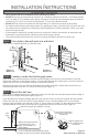
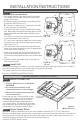
Fasten the wall can to ceiling rafters on any
two sides (See Figure 6) with a minimum of
4 screws (not included). You may need to
install an additional rafter perpendicular to
your ceiling rafters. The front edge of the wall
can must extend beyond the front edge of the
ceiling rafter(s) to match the drywall depth.
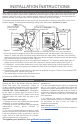
Route Supply Wires
STEP 2
Important: Supply connections must use wires suitable for at least 167˚F (75˚C) in the ceiling.
Route the electrical supply wire from the circuit breaker to the wall thermostat, and then to the wall can.
Remove a knockout from the wall can and attach the supply wire with a cable clamp connector (not
included) leaving a minimum of 6 inches wire lead (See Figure 3).
Continue to STEPS 4 and 5 above.
STEP 1
STEP 1
Wire connections
STEP 4
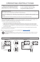
Install Grill
STEP 5
Attach grill with screws provided. If you have a built-in thermostat, slide thermo stat knob onto shaft. If
you have a model without a thermostat, snap in the grill plug provided.
Turn power on at the main disconnect panel.
Proceed to OPERATING INSTRUCTIONS.
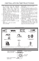
1. Your heater has two connection wires on the back.
Your supply wire has two connection wires and a
supply ground wire.
A. Connect supply ground wire to grounding screw
in wall can (See Figure 4 or 5).
B. Connect one supply wire to one heater wire with
a wire connector (not included):
For 240 or 208 volts, it doesn’t matter which heater
wire. Both supply wires (black and white) are hot. Wrap
supply (white) wire with black tape to identify it as hot
(Figure 4).
For 120 volts, connect the neutral (white) supply wire
to the white heater wire (Figure 5).
C. Connect the remaining supply wire to the remain-
ing heater wire with a wire connector (not included)
(See Figure 4 or 5).
2. Turn the heater back around and insert the bottom
edge of the heater assembly into the D-shaped tabs
at the bottom of the wall can.
3. Push all wires back into the bottom of the wall can.
Make sure connections are tight and that none of
the wires are caught between the motor and the wall
can.
4. Attach the heater assembly at top of the wall can
with screw provided.
CEILING MOUNT (MODEL CS ONLY)
Figure 6
(Model CS only)
wall can
6" (15.2 cm)
Minimum
6" (15.2 cm)
Minimum
A
B
C
A
B
C
Figure 5
120 volt
Figure 4
240 volt