TM Owner’s Manual & Installation Instructions Vented Range Hoods Models: CVW9304 and CVW9364 Contents Safety Information. . . . . . . . . . . . . . . . . . . . . . . . . . . . . . . 3 Installation Instructions. . . . . . . . . . . . . . . . . . . . . . . . . . 9 Using the Hood Controls . . . . . . . . . . . . . . . . . . . . . . . . . . . . . . . . . . . . . . 5 Chef Connect. . . . . . . . . . . . . . . . . . . . . . . . . . . . . . . . . . 5 Wi-Fi Connect . . . . . . . . . . . . . . . . . . . . . . .
THANK YOU FOR MAKING CAFÉ A PART OF YOUR HOME. We take pride in the craftsmanship, innovation and design that goes into every Café product, and we think you will too. Among other things, registration of your appliance ensures that we can deliver important product information and warranty details when you need them. Register your Café appliance now online. Helpful websites are available in the Consumer Support section of this Owner’s Manual.
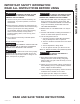
WARNING TO REDUCE THE RISK OF FIRE, WARNING TO REDUCE THE RISK OF INJURY ELECTRIC SHOCK OR INJURY TO PERSONS, OBSERVE THE FOLLOWING: TO PERSONS IN THE EVENT OF A RANGE TOP GREASE FIRE, OBSERVE THE FOLLOWING*: A. U se this unit only in the manner intended by the manufacturer. If you have questions, contact the manufacturer. A. S MOTHER FLAMES with a close-fitting lid, cookie sheet or metal tray, then turn off the burner. BE CAREFUL TO PREVENT BURNS.
SAFETY INFORMATION IMPORTANT SAFETY INFORMATION READ ALL INSTRUCTIONS BEFORE USING WARNING TO REDUCE THE RISK OF FIRE, ELECTRIC SHOCK OR INJURY TO PERSONS, OBSERVE THE FOLLOWING: A. I nstallation work and electrical wiring must be done by qualified person(s) in accordance with all applicable codes and standards, including fire-rated construction. WARNING TO REDUCE THE RISK OF FIRE, USE ONLY METAL DUCTWORK.
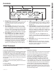
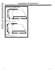
1 3 2 4 Fan Settings Off Low Delay Off Hold 3 Sec WiFi Pairing Med 7 High Light WiFi Boost Chef Connect To Pair Hold 3 Sec Hold 3 Sec 5 6 1. Rangehood Control Panel: The control panel 4. Light: Off/On/Night Light switch for the LED lights. 2. Fan On/Off: On/Off switch for the fan. The fan 5. Chef Connect: This is a Bluetooth® pairing feature is located under the front edge of the canopy. The position and function of each control button are noted below.
USING THE HOOD: Wi-Fi Connect Wi-Fi Connect Connecting your Wi-Fi Connect Enabled hood (on some models) Your Café hood is designed to provide you with two-way communication between your appliance and smart device. By using the Café Appliances Wi-Fi Connect features, you will be able to control essential hood operations such as fan speed, light functions, delay off and filter clean notification using your smartphone or tablet. This device complies with part 15 of the FCC Rules.
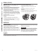
Be sure the circuit breaker is off and all surfaces are cool before cleaning or servicing any part of the vent hood. The baffle filters and drip trays are dishwasher safe and should be cleaned every month, depending on the usage of the hood Grease Drip Tray To install: Place and seat the drip trays into the designated hood track. Slide them left or right until all trays are side-byside in place in the track. To remove: Carefully, use the grease tray lip to lift the tray upwards and out.
CARE AND CLEANING: Surfaces / Lights / Filters Filters (Cont.) Charcoal Filter (for recirculation installation on select models only) NOTE: DO NOT rinse, or put charcoal filter in an automatic dishwasher. The charcoal filter is NOT included with the unit. Order Charcoal Filter UXCF91. It cannot be cleaned; it must be replaced. It is recommended that the charcoal filter be replaced every 6 months or if it is noticeably dirty or discolored.
If you have questions, visit us at cafeappliances.com or visit our website at: cafeappliances.ca. BEFORE YOU BEGIN Read these instructions completely and carefully. IMPORTANT — Save these ■ instructions for local inspector’s use. IMPORTANT — Observe all governing ■ codes and ordinances. ■ Note to Installer – Be sure to leave these instructions with the Consumer. ■ Note to Consumer – Keep these instructions for future reference.
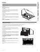
INSTALLATION PREPARATION Installation Preparation PRODUCT DIMENSIONS 12-1/4” 18” 21” 30” 30” Models Requires a 30” opening. 12-1/4” 18” 21” 36” 36” Models Requires a 36” opening. 10 49-2000706 Rev.
TOOLS AND MATERIALS REQUIRED (NOT SUPPLIED) PLAN THE INSTALLATION CAUTION To reduce risk of fire and to properly exhaust air, be sure to duct the air outside. Do not vent exhaust air into spaces within walls or ceilings or into attics, crawl spaces, or garages.
INSTALLATION PREPARATION Installation Preparation PARTS PROVIDED HARDWARE PACKAGE Locate the parts packed with the hood. Locate and check contents. A Top Damper (QTY: 4) 2.9mm x 6mm PZ screws. Used to attach the damper Motor 761Dia28 Grease Drip Trays B (QTY: 4) 8 x 1-3/4 AB screw. Used to mount the installation bar. Use 1/8" drill for pilot hole. Hood Body D (QTY: 4) M4 screws.
DUCT COVER REQUIREMENTS INSTALLATION DIMENSIONS Duct cover kits must be purchased separately. We recommend that the vent hood and duct cover (if used) be on site before final framing and wall finishing. This will help to accurately locate studs, ductwork and electrical service. The hood duct covers can be adjusted for different ceiling heights depending on the distance between the bottom of the hood and the cooktop (distance X). See Installation Height Table on the next page.
INSTALLATION PREPARATION Installation Preparation INSTALLATION HEIGHT TABLE CX8DC9SPDS OR CX8DC9SPWM Ceiling Duct Cover Kit up to 8ft. Ceiling Height (ft./in.) Installation over Gas Range Installation over Electric Range Vented Installation Height Vented Installation Height CX10DC9SPDS OR CX10DC9SPWM CX12DC9SPDS OR CX12DC9SPWM High Ceiling Duct Cover up to 10 ft. High Ceiling Duct Cover up to 12 ft. Installation over Gas Range Ceiling Height (ft./in.
ADVANCE PLANNING POWER SUPPLY Duct Install Planning IMPORTANT – (Please read carefully) ■ This hood is designed to be vented vertically through the ceiling with a 8” round duct or, horizontally through a wall with an 8”x12” duct transition and 12” round duct. ■ Use metal ductwork only. ■ Plan the route for venting exhaust to the outdoors. To maximize the ventilation performance of the vent system: 1. Minimize the duct run length and number of transitions and elbows. 2. Maintain a constant duct size. 3.
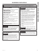
INSTALLATION INSTRUCTIONS Installation Preparation NEW CONSTRUCTION, PRE-PLANNING, OR REMODELING NOTE: For existing instruction, skip to the next section. FOR TOP VENTING FOR BACK VENTING ■ For ducted installation through the top, the 8” diameter hole for the duct in the ceiling must be centered 6-1/4” away from the finished rear wall in the installation space.
DETERMINE HOOD, DUCTWORK AND WIRING LOCATIONS • This hood can be installed onto the wall or underneath the soffit or cabinet. •F or installing the hood to soffit or cabinet, refer to page 19 for alternate mounting method. • A wall mounting template is included with the product for ease of installation. Follow the instructions below if the template is not being used.
INSTALLATION INSTRUCTIONS Installation Instructions 1 I NSTALL HOOD SUPPORT IMPORTANT: Framing must be capable of supporting 100 lbs. • Locate a minimum of 2 vertical studs for the installation bar by tapping drywall with a hammer or use a stud finder. •L evel the installation bar and center left to right above the marked line. Hold bar against the wall. 1 I NSTALL HOOD SUPPORT (cont.) • I nstall wall anchors (C) by tapping the anchors with a hammer to seat the teeth of the flanges into the wall.
3 I NSTALL HOOD ONTO WALL •P ull house wiring through knockout at the back or top of the hood. • Lift the hood and place over the hooks on the installation bar. Allow the hood to slide down into position. • Check to be sure the hood is level and centered. • Tighten wall anchor screws (C) to finish hood body installation to the wall. • Remove cover from junction box inside the hood.
INSTALLATION INSTRUCTIONS Installation Instructions 4 ( Alternate Mounting Method) INSTALL HOOD TO SOFFIT OR CABINET (Cont.) •D rill two 1/8” pilot holes at a distance of 10” from the back wall in the horizontal wood supports. This is the vertical distance between mounting keyholes and back wall as shown in Figure C •T he hood must also be secured to the back wall. Follow instruction on page 18, “Drill Bottom Mounting Hole Locations” section for installation to the back wall.
5 I NSTALL MOTOR 6 C ONNECT ELECTRICAL I) A lign the motor exhaust with the top damper as shown in the Figure A for top venting. In case of back venting, rotate the motor 90° to align with the back damper as shown in Figure B. Figure B Figure A Verify that power is turned off at the source. WARNING If house wiring is not 2-wire with a ground wire, a ground must be provided by the installer.
INSTALLATION INSTRUCTIONS Installation Instructions 7 C ONNECT DUCTWORK A. Vented Installation B. Recirculation (non-vented) Installation •C onnect the house ducting to the top damper as shown in Figure A. NOTE: A recirculation duct (WB34X30519), and Charcoal Filter (UXCF91), are not included with the hood and are necessary for recirculation installation. •F or back venting, connect the transition piece to the back damper and the house ducting to the transition as shown in Figure B.
8 I NSTALL DUCT COVERS •R efer to section “Duct Cover Requirements” section for duct cover accessory part numbers. •F ollow instructions included with the duct cover accessory to install duct covers. 9 I NSTALL GREASE TRAYS AND FILTERS • Remove protective film. • Place grease drip trays into slots. • I nstall the baffle filters. •S ee page 7 for instructions to install or remove filters and grease trays. 2 INSTALLATION INSTRUCTIONS Installation Instructions 1 49-2000706 Rev.
INSTALLATION INSTRUCTIONS Installation Instructions MAKE UP AIR TECHNOLOGY This operation must be performed by a qualified technician or installer. Note to Installers and Inspectors: This product comes equipped with a simple installation feature that limits maximum CFM levels in order to comply with certain local codes or regulations. This installation method may not be necessary for all installations, please refer to your local codes for further guidelines.
Save time and money! Review the charts on the following pages first and you may not need to schedule service. Problem Possible Cause What To Do Fan/Light does not operate when button is turned ON A house fuse may be blown or a circuit breaker tripped. Replace fuse or reset circuit breaker. Loud or abnormal airflow noise Wrong duct size used in installation. This hood requires 8” ducting to perform optimally. Using smaller duct pipe will cause reduced venting.
LIMITED WARRANTY Café Vented Range Hood Limited Warranty cafeappliances.com All warranty service is provided by our Factory Service Centers, or an authorized service technician. To schedule service online, visit us at cafeappliances.com/service. Please have your serial number and your model number available when scheduling service. Servicing your appliance may require the use of the onboard data port for diagnostics.
Looking For Something More? Café offers a variety of accessories to improve your cooking and maintenance experiences! Refer to the Consumer Support page for website information.
CONSUMER SUPPORT Consumer Support Café Website Have a question or need assistance with your appliance? Try the Café website 24 hours a day, any day of the year! You can also shop for more great Café products and take advantage of all our on-line support services designed for your convenience. In the US: cafeappliances.