
Repair manual


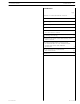


Manuals for repairs are split into Parts and Sections, each one of which is marked by a numeral; the contents of these sections are
indicated in the general table of contents.
The sections dealing with things mechanic introduce the specifications, tightening torque values, tool lists, assembly
detaching/reattaching operations, bench overhauling operations, diagnosis procedures and maintenance schedules.
The sections (or parts) of the electric/electronic system include the descriptions of the electric network and the assembly’s
electronic systems, wiring diagrams, electric features of components, component coding and the diagnosis procedures for the
control units peculiar to the electric system.
Section 1 describes the engines illustrating its features and working in general.
Section 2 describes the type of fuel feed.
Section 3 relates to the specific duty and is divided in four separate parts:
1. Mechanical part, related to the engine overhaul, limited to those components with different characteristics based on the relating
specific duty.
2. Electrical part, concerning wiring harness, electrical and electronic equipment with different characteristics based on the relating
specific duty.
3. Maintenance planning and specific overhaul.
4. Troubleshooting part dedicated to the operators who, being entitled to provide technical assistance, shall have simple and direct
instructions to identify the cause of the major inconveniences.
Sections 4 and 5 illustrate the overhaul operations of the engine overhaul on stand and the necessary equipment to execute such
operations.
The appendix contains a list of the general safety regulations to be respected by all installation and maintenance engineers in order
to prevent serious accidents taking place.
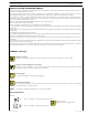
The manual uses proper symbols in its descriptions; the purpose of these symbols is to classify contained information. In particular,
there have been defined a set of symbols to classify warnings and a set for assistance operations.
General danger
It includes the dangers of above described signals.
Danger of serious damage for the assembly
Failure to comply, both fully or in part, with such prescriptions will involve serious damage to the assembly and may
sometimes c ause the warranty to become null and void.
Environment protection
Moreover, it describes the correct actions to be taken to ensure that the assembly is used in such a way so as to protect
the environment as much as possible.
Danger for persons
Missing or incomplete observance of these prescriptions can cause serious danger for persons’ safety.
SYMBOLS - Warnings
It indicates an additional explanation for a piece of information.
!
NOTE
PREFACE TO USER’S GUIDELINE MANUAL
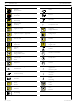
Service operations
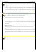
Example
Ø 1 = housing for connecting r od small end bush
Ø 2 = housing for connecting rod bearings
α
Tighten to torque
Tighten to torque + angular value
1
∅
∅
2
INTRODUCTION 3
F3C CURSOR ENGINES
Print P2D32C005 E Base - May 2007