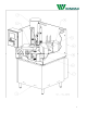
Model101 Rot aryI ndexPackagi ngMachi ne Mach.No.
Table of Contents Main Bill of Materials………………………………………..…...………..3 Machine Control Operation……………………………………...………..5 Base Unit…………………………………………………………...……...15 Cup Place Station…………………………………………….…...………40 Fill Station…………………………………………………………...…….47 Foil Place Station..………………………………………………...………51 Heat Seal Station…………………………………………..……...………55 Unload Station…………………………………………………….....……59 Air Electrical………………………………………………………………63 Tooling Package…………………………………………………………...66 Perimeter Guarding……………………………………………………....
Bill of Material - Manufactured Assembly Part No.: 101-119-2950 Unit Description: Machine - Complete Model: Single Lane - Small, Liquid Fill Release Date: 8/4/2009 0:00 ITEM QTY. PART NO. DESCRIPTION 1 1 000-000-0002 Machine Base B.O.M. 2 1 101-001-0006 Station 01Cup Load B.O.M. 3 1 101-002-0006 Station 02 Fill B.O.M. 4 1 101-004-0001 Station 04 Foil Place B.O.M. 5 1 101-005-0004 Station 05 Seal B.O.M. 6 1 101-006-0001-A Station 06 Unload B.O.M.
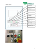
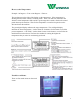
Machine Control Touch Screen Temperature Controller Machine Power On Cycle Start Cycle Stop E-Stop Reset Machine Cycle Speed Zone On/OFF (filler/foil place/heater) Emergency Stop 5
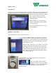
Main Controls: Powering Up: Ensure lower guards and perimeter guards are in place. Plug power into the machine and connect the air pressure. Turn the power switch to the “ON” position. The touch screen should come on and will indicate "Power Off." Now press the green "E-Stop Reset" button on the panel above the "Emergency Stop." Indicator should now read “Powering Up” and “E-Stop Reset” button should now be lit up green. Next, verify that the machine is in Auto or Manual Mode. Manual vs.
Optimum cycle speed is determined by a variety of factors. During run-off you should have been given optimum cycle speeds. However, a good rule of thumb is, the faster the machine, the higher the temperature and/or the greater the pressure needed for quality seals. Speed may also be dictated by the filling process. Optimum settings for various products and various container styles may be stored in the Recipe menu of the touch screen HMI.
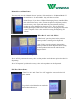
How to set the Temperature: Example: 80 Degrees = F 80 or 200 Degrees = F200 etc. The two buttons on the right of the display set the temperature. If the temperature is flashing then the heater control is in tuning mode. There is an alarm on the heater that when the actual temperature falls outside a given range then it sends a fault to the control panel that stops the machine. Wait for the temperature to come back up and reset the fault and restart the machine.
Manual Screen Menu Items: You may only use the “Manual Screen” options, if the machine is “In Manual Mode” If the machine is “In Auto Mode” they will have no effect. Prime/ Purge: If you have a Wilpack Packaging factory installed filler, this will turn the rotary valve, actuate the piston to dispense product, turn the rotary valve again and return the piston thereby drawing product up to be dispensed on the next cycle.
Maintenance Screen Menu Items In this area is the “Suck Back Time.” This is the interval between the return of the piston and the closing of the rotary valve. Timing this correctly for viscous products will suck a portion of the product from the dispensing nozzle back into the filler so that it does not drip on the dial plate or container sealing surfaces in between fill operations. Touching the actual time brings up an input screen for changing the time.
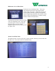
Recipe Screen Menu Items * Note: the flashing red text reads…”changing a recipe has no effect on the machine” This area is for reference only. There is room for up to 10 recipes. Use “Prev Recipe” and “Next Recipe” to toggle between recipes. If you touch a recipe category name, an input screen will appear to change the name of that category. If you touch a recipe value, an input screen will appear to change the value of the category.
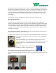
Machine Operation Basics Home Position: Proximity Sensor Cam Arm If looking at the underside of the machine from the eject side, look for the Cam Arm and the proximity sensor located nearby. When the arm is back far enough to interact with the proximity sensor (the sensor will be lit up) then the machine is in “Home Position.” Cup drop Sensor In “Home Position” the machine is looking for a cup with the cup drop sensor located just under the dial plate where the cup drops.
the foil place station, then the logic will override this and not allow the foil to be picked up. There is no sense placing a foil if there is no cup. Foil Place Proximity Sensor: If looking at the underside of the machine from the foil place and heat seal side of the machine you should see a proximity sensor that interacts with the foil place shaft.
Foil Place and Table Detent Airflow Sensors Table Detent Airflow Sensor (The larger of the two) Foil Place Airflow Sensor (The smaller of the two) The foil place sensor detects airflow when there is a vacuum created and holding a foil. If air is flowing then it indicates a foil was not picked up (maybe the stack was empty) or a foil fell off before the vacuum was shut off (maybe the vacuum was too weak). Regardless, if there is supposed to be a vacuum and there is airflow it will create a fault.
Bill of Material - Manufactured Assembly Part No.: 000-000-0002 Unit Description: Base Unit Model: Universal Release Date: 10/1/2009 0:00 ITEM QTY. PART NO. 1 2 3 4 5 6 7 8 1 1 1 1 1 1 1 1 000-000-A000-A 000-000-B000 000-000-C000 000-000-A001 000-000-A004 000-000-A005 000-000-A006 000-000-A008-B DESCRIPTION Base Sub-Ass'y. Drive Sub-Ass'y. Cam Sub-Ass'y. Cup Load Sub-Ass'y. Foil Place Sub-Ass'y. Seal Sub-Ass'y. Unload Sub-Ass'y. Electrical Panel Sub-Ass'y. B.O.M. B.O.M. B.O.M. B.O.M. B.O.M.
Base Unit 000-000-A000-A The Base Unit consists of 4 legs and the frame with base and top units. The three stainless steel sides are held on with the P4 detents and the two sides #14 are held in place with a bolt. Notice that Item 10 (Qty 2), is the last piece to be fitted over the other two sides.
Bill of Material - Manufactured Assembly Part No.: 000-000-A000-A Unit Description: Base Unit Model: Universal Release Date: 8/31/2009 0:00 ITEM QTY. PART NO.
Bill of Material - Purchased Assembly Part No.: 000-000-A000-A Unit Description: Base Unit Model: Universal Release Date: 8/31/2009 0:00 ITEM QTY. PART NO.
Base Unit 000-000-B000 Drive Sub Assembly The Camco Drive unit and Baldor Motor are the central drive units of the machine. The center shaft protruding up-wards from the motor is fitted with a air seal. Should the dial be broken loose from its home position, the detents, P7, disengage, and the air pressure switch (not-shown) senses the loss of pressure. This pressure switch (not-shown) can only be reset in the home position. Again, this is a single position on the dial.
Bill of Material - Manufactured Assembly Part No.: 000-000-B000 Unit Description: Base Unit Model: Universal Release Date: 04/22/03 ITEM QTY. PART NO. 1 2 3 4 5 6 7 8 9 10 1 1 2 1 1 1 1 1 1 1 000-0417 000-0604 000-0656 000-0959 000-0960 000-0961 000-0962 000-0963 000-0982 000-1554 Drive Sub Assembly DESCRIPTION Indexer Support Bracket Mount Prox.
Bill of Material - Purchased Assembly Part No.: 000-000-B000 Unit Description: Base Unit Model: Universal Release Date: Drive Sub Assembly 4/22/2003 0:00 ITEM QTY. PART NO.
Base Unit 000-000-C000 This is the lifting unit for the completed part unload station. The P5, sensor, (as noted in Base Unit, Camco Drive) reads at Item 6, on the cam arm. Item 10, is attached directly to the Camco Drive. Grease zirks are located on two (2) of the P1 (Pillow Block) locations. Clean and lubricate Item 5, Cam Paths, weekly.
Bill of Material - Manufactured Assembly Part No.: 000-000-C000 Unit Description: Base Unit Model: Universal Release Date: 04/22/03 ITEM QTY. PART NO.
Bill of Material - Purchased Assembly Part No.: 000-000-C000 Unit Description: Base Unit Model: Universal Release Date: 4/22/2003 0:00 ITEM QTY. PART NO.
Cup Load Sub Assembly 000-000-A001 The Cup Load Station is driven by this unit. The chain that is attached to the Camco Drive powers this station. The chain has an idler, P5, for take up of slack. Grease zirks are located at P4, and each of the four (4) P1 (Pillow Block), locations.
Bill of Material - Manufactured Assembly Part No.: 000-000-A001 Unit Description: Cup Load Sub Assembly Model: Universal Release Date: 04/22/03 ITEM QTY. PART NO.
Bill of Material - Purchased Assembly Part No.: 000-000-A001 Unit Description: Cup Load Sub Assembly Model: Universal Release Date: 04/22/03 ITEM QTY. PART NO.
Foil Place Sub Assembly 000-000-A004 This eccentric drive raises and lowers the foil place suction cup. There are no height adjustments on this unit.
Bill of Material - Manufactured Assembly Part No.: 000-000-A004 Unit Description: Foil Place Sub Assembly Model: Universal Release Date: 4/22/2003 0:00 ITEM QTY. PART NO.
Bill of Material - Purchased Assembly Part No.: 000-000-A004 Unit Description: Foil Place Sub Assembly Model: Universal Release Date: 4/22/2003 0:00 ITEM QTY. PART NO.
Heat Seal Sub Assembly 000-000-A005 This unit is driven by the base unit lift cam and raises and lowers the heat seal. There is no height adjustment on this unit.
Bill of Material - Manufactured Assembly Part No.: 000-000-A005 Unit Description: Heat Seal Sub Assembly Model: Universal Release Date: 4/22/2003 0:00 ITEM QTY. PART NO.
Bill of Material - Purchased Assembly Part No.: 000-000-A005 Unit Description: Heat Seal Sub Assembly Model: Universal Release Date: 4/22/2003 0:00 ITEM QTY. PART NO.
Unload Sub Assembly 000-000-A006 This unit is driven by the base unit lift cam and raises and lowers the unload shafts. There is no height adjustment on this unit. NOTE: Item 3 and Item 4 are used as a reset bar for the unload shafts. This unit may need to be raised or lowered for proper reset.
Bill of Material - Manufactured Assembly Part No.: 000-000-A006 Unit Description: Unload Sub Assembly Model: Universal Release Date: 4/22/2003 0:00 ITEM QTY. PART NO.
Bill of Material - Purchased Assembly Part No.: 000-000-A006 Unit Description: Unload Sub Assembly Model: Universal Release Date: 4/22/2003 0:00 ITEM QTY. PART NO.
Bill of Material - Manufactured Assembly Part No.: 000-000-A008-B Unit Description: Electrical Panel Sub Assembly Model: Universal Release Date: 5/27/2010 0:00 ITEM QTY. PART NO.
Bill of Material - Purchased Assembly Part No.: 000-000-A008-B Unit Description: Electrical Panel Sub Assembly Model: Universal Release Date: 5/27/2010 0:00 ITEM QTY. PART NO.
Cup Load 101-001-0006 To begin adjustments, remove the cup accumulation cylinders from the top of the load station. NOTE: The adjustment screws (Cup Drop Cams) are on one way bearings. (The screws only manually turn counter-clockwise and not clockwise). To adjust the screws for proper cup loading, point the leading edge of the screw (start point of the groove) towards the center of the cup. Each screw should have its leading edge pointing at the center of the cup.
Bill of Material - Manufactured Assembly Part No.: 101-001-0006 Unit Description: Cup Load Model: Single Lane Fixed - Small - Adjustable Height Release Date: 9/29/2009 0:00 ITEM QTY. PART NO.
Bill of Material - Purchased Assembly Part No.: 101-001-0005-A Unit Description: Cup Load Model: Single Lane Fixed - Small Release Date: 9/29/2009 0:00 ITEM QTY. PART NO. P1 P2 P3 P4 P5 P6 P7 P8 P9 P10 P11 2 12 8 4 1 1 1 1 5 1 4 P01-0005 P01-0006 P01-0015 P01-0021 P01-0022 P01-0023 P01-0024 P01-0028 P01-0029 P01-0030 P01-0034 DESCRIPTION Bearing Bearing O" Ring (010) Roller Clutch #25 Stn. Stl. Connector Link #25 Stn. Stl.
Bill of Material - Manufactured Assembly Part No.: 101-002-0006 Unit Description: Fill - .5- 4 Oz. Large Hopper Model: Single Lane Release Date: 5/27/2010 0:00 ITEM QTY. PART NO.
Bill of Material - Purchased Assembly Part No.: 101-002-0006 Unit Description: Fill - .5- 4 Oz. Large Hopper Model: Single Lane Release Date: 5/27/2010 0:00 ITEM QTY. PART NO.
Bill of Material - Manufactured Assembly Part No.: 101-004-0001 Unit Description: Foil Place Model: Single Lane - Small Release Date: 2/12/2003 0:00 ITEM QTY. PART NO.
Bill of Material - Purchased Assembly Part No.: 101-004-0003 Unit Description: Foil Place Model: Single Lane - Small Release Date: 2/12/2003 0:00 ITEM QTY. PART NO.
Bill of Material - Manufactured Assembly Part No.: 101-005-0004 Unit Description: Heat Seal Model: Single Lane - Small Release Date: 5/27/2010 0:00 ITEM QTY. PART NO.
Bill of Material - Purchased Assembly Part No.: 101-005-0004 Unit Description: Heat Seal Model: Single Lane - Small Release Date: 5/27/2010 0:00 ITEM QTY. PART NO. P1 P2 P3 P4 P5 P6 P7 P8 P9 P10 P11 P12 Not Shown Not Shown Not Shown 2 2 1 2 1 1 3 3 1 1 1 3 7' 1 1 P05-0003 P05-0007 P05-0008 P05-0009 P05-0011 P05-0012 P05-0013 P05-0015 P05-0026 P05-0029 P05-0028 008-3HWL6 P05-0011 P05-0031 DESCRIPTION Stn. Stl.
Bill of Material - Manufactured Assembly Part No.: 101-006-0001-A Unit Description: Unload w/Boot Model: Single Lane - Small Release Date: 9/18/2005 0:00 ITEM QTY. 1 2 3 4 5 6 7 8 9 10 11 12 13 14 15 16 17 18 19 20 1 1 1 1 1 1 1 1 1 1 1 1 2 1 1 1 1 1 1 1 PART NO.
Bill of Material - Purchased Assembly Part No.: 101-006-0001-A Unit Description: Unload w/Boot Model: Single Lane - Small Release Date: 9/18/2005 0:00 ITEM QTY. PART NO.
Bill of Material - Manufactured Assembly Part No.: 101-008-0005 Unit Description: Electrical Pnuematic Model: Single Lane - Small Release Date: ITEM QTY. PART NO.
Bill of Material - Purchased Assembly Part No.: 101-008-0005 Unit Description: Electrical Pnuematic Model: Single Lane - Small Release Date: ITEM QTY. PART NO.
Bill of Material - Manufactured Assembly Part No.: 101-009-2950 Unit Description: Tooling Pack Model: Single Lane -Small Release Date: 8/14/2009 0:00 ITEM QTY. PART NO.
101-009-2950 Tooling Pack Designation: Container: 75mm Winpak DP Series Seal: 75.
Bill of Material - Manufactured Assembly Part No.: 000-010-0006-A Unit Description: Perimeter Guard Model: Universal Release Date: 5/28/2010 0:00 ITEM QTY. PART NO.
Bill of Material - Purchased Assembly Part No.: 000-010-0006-A Unit Description: Perimeter Guard Model: Universal Release Date: 5/28/2010 0:00 ITEM QTY. PART NO. P1 P2 P3 P4 P5 P6 P7 1 4 4 4 16 16 16 P10-0018 P10-0019 P10-0020 P10-0021 P10-0022 P10-0023 P10-0024 DESCRIPTION Magnetic Switch Controller AWAX 26XXL Magnetic Switch MAK-4256-3 Magnetic Switch Sensor TK42-CD/2 Cord Grip Acorn Nut 1/4-20 Acorn Nut #8-32 Slotted Shoulder Screw 5/16 x 1/2 lg.
Apendix A Electrical.
Apendix B Camco Indexer Manual.
® The Driving Force in Automation GENERAL SERVICE MANUAL INDEX DRIVES “WARNING” “WARNING” This is a controlled document. It is your responsibility to deliver this information to the end user of the CAMCO indexer. Failure to deliver this, could result in your liability for injury to the user or damage to the machine. For copies of this manual call your Customer Service Representative 800/645-5207.
Table of Contents Introduction ............................................................................................................2 How To Use Your Service Manual ..........................................................................2 Warranty ............................................................................................................2, 3 Interpretation of Index Drive Model Numbers ....................................................3, 4 Index Drive Service Data ................
INTRODUCTION CAMCO Index Drives are engineered and manufactured to very high tolerances which necessitate careful inspection and maintenance. This manual will act as a general guide to lubrication, trouble shooting and general information about index drives. In addition to this General Service Manual CAMCO has other service manuals devoted to the specific model CAMCO index drive you are using. The specific model service manuals deal with disassembly and assembly of the major components.
Our obligation under the foregoing is limited to replace free of charge, including the lowest transportation cost, but not including installation or any other charges, any part that our inspection shows to be defective provided that the part was properly installed, suitably maintained and not subject to misuse or abuse, and further provided that the defective parts are returned to our plant within one (1) year after delivery by us. Written permission for such return must first be obtained from CAMCO.
5. Cam motion in degrees. The cam is divided into two basic parts, motion and dwell. Motion is the angular segment in which the cam does its work rotating the output shaft one complete stop. After motion is complete the cam is considered to be in dwell for the reminder of the 360 degree rotation. Dwell means there is no motion taking place at the output of the Index Drive even though the input shaft continues to rotate.
OIL CHANGE An oil change is required every 2000 hours of operation, or every six months whichever occurs first. Where operating conditions are severe, such as rapid rise and fall in temperature of the indexer housing (which is accompanied by sweating of the inside walls with a resulting formation of sludge), where operation is in moist and dusty atmospheres, or in the presence of chemical fumes, it may be necessary to change the oil in intervals of one to three months.
INDEX DRIVE OIL CAPACITIES - EST. OIL CAP. (NORMAL MOUNTING POSITION)* MODEL NO. U.S. Metric MODEL NO. Metric 150RPP 300RPP U.S. ON LINE 2 1/2 Qt. 4 Qt. -----250P Quart 3/4 Qt. (liter) (.7) 387P 512P 2 Qt. 5 Qt. (1.9) (4.7) 500RPP 900RPP 10 Qt. 48 Qt. (9.5) (45) 662P 900P 10 Qt. 20 Qt. (9.5) (19) 950E 1150E CF CF (CF) (CF) 1200P 1800P 48 Qt. 95 Qt. (48.6) (90.3) 1550E 2050E CF 45 Gal (CF) (166 L) 350RG 500RG 1 1/2 Qt. 5 Qt. (1.4) (4.7) 2750E 700RG 75 Gal 10 Qt. 277 L) (9.
6. Check splines and keyways -- smooth any sharp edges and when necessary protect the seal lip with an assembly sleeve or shim stock. Round the edges of the spline or keyway as much as possible and lubricate with a hard, fibrous grease. 7. Check seal direction -- make sure that the new seal faces in the same direction as the original. Generally, the lip faces the lubricant or fluid to be sealed. 8. Prelubricate the sealing element -- before installation by wiping with lubricant being retained. 9.
GEAR REDUCER LUBRICATION DATA OIL LEVEL Most reducers are furnished with a "bulls eye" type sightglass or a pipe plug to indicate oil level. In either case an oil level tag is affixed to the reducer near the oil level indicator. Oil level should be checked with the unit stopped. Estimated oil capacities for standard reducers are listed on page 13. CAUTION: CAMCO ships all gear reducers without oil (except the 180SM, R225 and R260). Be sure to fill to proper level prior to startup.
OIL CAPACITY MODEL CAPACITY (liter) Morse 13ED Morse 15ED Morse 18ED Morse 20ED Morse 25ED Morse 40GSF 7200C 7250C 7300C 7350C 7400C 7500C 7600C 7 0z. 7.5 oz. 12 oz. 14 oz. 1 qt. 3 1/2 qt. 1 qt. 1 qt. 1 1/2 qt. 3 1/2 qt. 1 gal. 1 3/4 gal. 2 3/4 gal. (.2) (.2) (.4) (.4) (.9) (3.3) (.9) (.9) (1.4) (3.3) (3.8) (6.6) (10.4) MODEL CAPACITY Morse 18GSF Morse 20GSF Morse 25GSF Morse 30GSF Morse 35GSF 12 oz. 24 oz. 1 1/4 qt. 2 qt. 3 qt. (.4) (.7) (1.2) (1.9) (2.8) Morse 50GSF Morse 60GSF 1 3/4 gal.
OVERLOAD CLUTCH GENERAL The CAMCO (plunger type) overload clutch is a reliable minimum service overload device requiring very little attention (in a semi-clean environment) during its service life. The environment is an important factor in the successful functioning of this device. A dusty or corrosive environment may require special preparation or attention. (Contact CAMCO for special modifications). High humidity, contaminants, or wash down applications may also require special protection.
3. Long Term Storage (Outdoors) for Periods up to One Year. Proceed as in (2) above with the following additions. (a) After filling the unit with oil, plug the breather hole with a pipe plug and wire the breather hole the unit. (b) Coat all exposed shafting with long term rust preventative. 4. Extended Storage periods Exceeding One Year. (a) Coat all exposed shafts with a long term rust preventative. (b) Place the unit in a heavy plastic bag and put approximately 1/2 oz. #260 "VPI" powder in the bag.
SYMPTOM: LOOSENESS IN EACH DWELL 1. Camshaft is loose in bearings. Check for end play in input shaft. Adjust shims on bearing caps. See individual service manual for preload setting procedures. 2. Cam is loose on shaft. Usually repaired at factory. 3. Cam is broken. (This happens very seldom and is an indication of an overload application or a jam-up). 4. Unit was very heavily overloaded and all bearings loosened up. Rework required. 5. All followers are worn. Rebuilding by factory is best remedy.
SYMPTOM: OUTPUT MOVEMENT IS ERRATIC AND VIBRATING 1. Input does not run at a constant velocity. The prime objective of a good input connection to an Index Drive is to maintain a constant shock free velocity (see input recommendations). Motor running too slow could also cause an erratic output. 2. Output connections loose flexing, or winding up. Check all connections (see recommended output connections). 3. Excessive friction drag on output. Disconnect indexer and investigate friction torque. 4.
6. Permanent magnet motors fulfill two objectives, low cost and low inertia, but are at a disadvantage for flywheel energy. This is especially serious for large dial and reciprocating applications. CAMCO does not recommend operating permanent magnet motors below 1000RPM, and if loads are very heavy we would like to see 1500RPM or more. Failure to maintain these minimum speeds will result in erratic input speeds and unpredictable torque levels. 7. Air and hydraulic motors can cause considerable problems.
HOW TO ORDER PARTS Please refer to Parts List applicable to your specific model as shown in the specific model service manual. This Parts List is for a standard Index Drive. If you feel your drive in nonstandard or you are in doubt you should contact CAMCO Customer Service (847) 459-5200 and request a bill of material for your specific unit (based on serial number).
Type 2 motions require double-lobe trip cams since one revolution of the input will produce 2 dwells. Type 2 units are typically used when a higher number of stops are required.Please remember that CAMCO cannot preset the trip cam. Every customer has different requirements which make standardization very difficult. Another potential problem is double indexing. This can happen if limit switch does not close the contacts for a sufficient peroid necessary to energize the holding relay.
HOW TO RETURN FOR REPAIR Please contact Customer Service Department in Wheeling, Illinois at (847) 459-5200 for a "Return Material Authorization" Number (RMA#). The following information is required of a unit for repair, conversion or warranty. 1. 2. 3. 4. 5. 6. 7. 8. 9. Purchase order number Customer name Customer billing address Customer shipping address Person to contact, upon inspection, with delivery and price.
INDEXER WEIGHTS EFFECTIVE: 4/12/96 SUPERSEDES: 3/29/96 Model Right Angle Weight-Lbs. (Kg) Model Roller Gear Weight-Lbs. (Kg) 301RA 400RA 401RA 512RA 662RA 663RA 900RA 1200RA 15 33 55 80 160 130 220 850 350RG 500RG 600RG 700RG 601RDM 902RDM 1305RDM 1800RDM 425RD 800RD 1301RD 1801RD 35 350 390 400 70 130 305 1400 110 450 1000 2400 Model Parallel Weight-Lbs.
TORQUE VALUES FOR LOCKNUTS TIGHTENING TORQUE FOR CAM FOLLOWER LOCKNUTS. Follower Thread Size Torque - Ft Lbs. (Nm) 7/16 (H14) #10-32 1.2 (1.5 Nm) 1/2 (H16) 1/4-28 3 (4) 5/8 (H20) 5/16-24 7.
RECOMMENDED TIGHTENING TORQUE VALUES FOR CAPSCREWS Bolt Size (UNF or UNC) Into Aluminum **Torque Ft/Lb (NM) Into Steel **Torque Ft/Lb (Nm) 1/4 5/16 5 9 (7 Nm) (12) 7 !4 (9 Nm) (19) 3/8 7/16 16 26 (22) (35) 25 40 (34) (54) 1/2 9/16 42 58 (57) (79) 65 80 (88) (108) 5/8 3/4 85 143 (115) (194) 110 220 (150) (298) 7/8 1 228 345 (310) (468) 350 530 (475) (720) 1 1/8 1 1/4 430 598 (583) (810) 660 920 (895) (1250) 1 1/2 1065 (1440) 1640 (2225) Note: Torque values are for non-l
USA 6/99 0061 100
Warranty & Parts Warranty The Wilpack Machines are guaranteed on all machined parts by Wilpack against defects for a period of twelve months. All purchased components such as bearings, drive motor, gear box, etc. will be guaranteed to the customer as guaranteed to Wilpack. NOTE: If physical alterations or changes are made to the machine by anyone other than Wilpack, the warranty is immediately null and void unless written permission is given by Wilpack. This will insure our continuous high standards.
Notes: 102
Notes: 103