
Use and Care Manual


Operating Instructions
Installation (Continued)
INSTALLING A SHUT-OFF VALVE
Ashut-offvalveshouldbeinstalledonthedischargeportofthe
tank to control the air flow out of the tank� The valve should be
located between the tank and the piping system�
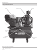
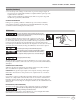
AsshowninFigure3,assembletheoutletvalvetothepipe
nipple� Install assembled valve in either end of the tank� Use
thread sealant tape on threads of pipe nipple to prevent air leaks�
Never install a shut-off valve between the
compressor pump and the tank. Personal injury
and/or equipment damage may occur. Never use reducers in discharge
piping.
When creating a permanently installed system to distribute
compressed air, find the total length of the system and select
pipesizefromthechart.Buryundergroundlinesbelowthe
frost line and avoid pockets where condensation can gather and
freeze.Applyairpressuretothepipinginstallationandmake
surealljointsarefreefromleaksBEFOREundergroundlinesare
covered.Beforeputtingthecompressorintoservice,findand
repair all leaks in the piping, fittings and connections�
PIPING
Never use plastic (PVC) pipe for compressed air.
Serious injury or death could result.
Anytube,pipeorhoseconnectedtotheunitmustbeableto
withstandthetemperaturegeneratedandretainthepressure.All
pressurized components of the air system must have a pressure
rating of 200 psi or higher� Incorrect selection and installation
of any tube, pipe or hose could result in bursting and injury�
Connect piping system to tank using the same size fitting as the
discharge port�
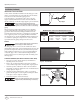
STARTER SOLENOID (UNIT WITH ELECTRIC START ONLY)
1� Disconnect negative cable from battery terminal before
attaching wires to the solenoid�
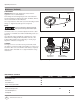
2. Removethe1/4inchnutfromtheleftstud.Donotmake
contact with the right stud to avoid possible engine ignition�
3. Attachthepositive(red)batterycabletotheleftstudand
reinstall the 1/4 inch nut� Tighten the nut one full turn after it
isfingertight(SeeFigure5).
4. Attachthenegative(black)batterycabletoaconvenient
ground� The best place is at the engine mounting bolt� Other
secure places on the engine are suitable�
5. Reattachthenegativecabletothebattery.
Failure to install appropriate water / oil removal
equipment may result in damage to machinery
or workpiece.
www.CH-Commercial.com
6
MINIMUM PIPE SIZE FOR COMPRESSED AIR LINE
CFM
Length Of Piping System
25 feet 50 feet 100 feet 250 feet
10 1/2 inch 1/2 inch 3/4 inch 3/4 inch
20 3/4 inch 3/4 inch 3/4 inch 1 inch
40 3/4 inch 1 inch 1 inch 1 inch
Figure 4 - Shut-off Valve
Figure 3 - Shut-off Valve Install
Outlet Valve
Pipe Nipple
Discharge Port
Figure 5 - Starter Solenoid
Left Stud
Positive (Red)
Battery Cable
Fuel Tank