INSTALLATION OPERATION AND SERVICE MANUAL MODULATING MICOFLAME GRANDE GAS FIRED COMMERCIAL COPPER TUBE BOILERS FOR HYDRONIC HEATING Non-Condensing Models; MFH2010, 2500, 3000, 3500, 4000 Condensing Models; MFH2012, 2502, 3002, 3502, 4002 HOT WATER SUPPLY Non-Condensing Models; MFW2010, 2500, 3000, 3500, 4000 Condensing Models; MFW2012, 2502, 3002, 3502, 4002 WARNING: If the information in these instructions is not followed exactly, a fire or explosion may result causing property damage, personal injury or
Table of Contents 1 2 3 4 5 6 6.1 6.2 6.3 6.6 6.5 7 7.1 7.2 7.3 7.4 7.5 7.6 7.7 7.8 7.9 7.9.1 7.9.2 8 8.1 8.2 8.3 8.4 8.5 9 9.1 9.2 9.3 9.4 9.5 9.6 9.7 9.8 9.9 9.10 9.11 9.12 10 10.1 10.2 11 GENERAL INFORMATION ................................................................................................................................. 1 LOCATION .......................................................................................................................................................
11.1 11.2 11.3 12 12.1 12.2 12.3 13 14 15 16 16.1 17 MAIN BURNER .............................................................................................................................................. 36 REMOVAL OF COMBUSTION CHAMBER LINING ............................................................................................. 38 PILOT BURNER ..............................................................................................................................................
1 warrantable Excessive pitting and erosion on the inside of the copper tube may be caused by high water velocity or the use of an undersized boiler for a DHW application and is not covered by warranty. Using or storing corrosive chemicals in the vicinity of this boiler can rapidly attack the copper tubes and voids warranty. The primary heat exchanger of this boiler is intended to operate under non-condensing conditions.
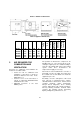
Figure 1: Appliance Dimensions Table 3: Appliance Dimensions B' Dia. Venting Condensing or Sidewall Standard Air Inlet (Optional) “L” W' ‘S’ 34 ⅝” 54 ¾” 33 3/8” 34 ⅝” 79” 58” 34 ⅝” 79” 58” 34 ⅝” 103” 81 ¾” 34 ⅝” 103” 81 ¾” Outdoor “K” 68” 72” 72” 72” 72” Gas Connection 3 “I” 6” 6” 6” 6” 6” Water Connection Model MF2010 MF2500 MF3000 MF3500 MF4000 E' Dia.
4 ELECTRICAL WIRING 5 NORMAL GAS SUPPLY This appliance is intended to operate at inlet gas pressures not exceeding 1/4 PSI (7“W.C.) when firing with natural gas. If higher pressures are present, consult the gas company for correction.
6 do not operate a summer exhaust fan. Close fireplace dampers. d) Place in operation the appliance being inspected. Follow the lighting instructions. Adjust thermostat so that appliance operates continuously. e) Test for spillage at the draft control device relief opening after 5 minutes of main burner operation. Use the flame of a match or candle or smoke from a cigarette.
A qualified service technician should follow this procedure when inspecting and cleaning the heat exchanger and vent pipe. The MicoFlame Grande is category 1, 85% efficient when supplied as a non-condensing appliance. When supplied with the optional condensing cartridge, the MicoFlame Grande is 95% efficient and is considered to be a category II or IV appliance. Three venting options are available for this appliance in both condensing and non-condensing configurations. See Figure 2 for details.
6.2 STANDARD VENTING 6.6 The non-condensing 85% efficient MicoFlame Grande is a category I appliance and is approved for venting into a common chimney provided it is in good condition and meeting the local Codes. Typically, the chimney will be ‘B’ vent or brick with clay or metal liner. If the chimney height is much greater than 30 feet or if drafts are in excess of negative 0.05” W.C., it will be necessary to provide a single acting barometric damper directly above the vent collar.
A qualified professional using a proven ventsizing program with input of accurate operating parameters must properly calculate sizing of the venting system. In applications where flue gas temperatures are lower than can support a Category II with conventional negative draft, it will be determined at the venting design stage that a positive pressure will be developed in the vent.
7.1 The appliance must be installed so that the gas ignition system components are protected from water (dripping, spraying, rain, etc.) during appliance operation and service (circulator replacement, control replacement, etc.) PROTECTION DEVICES PRESSURE RELIEF VALVE (shipped loose) This appliance is supplied with a relief valve sized in accordance with ASME Boiler and Pressure Vessel Code, Section IV (“Heating Boilers”).
FLOW SWITCH (shipped loose) and will allow easier servicing of the appliance under severe weather conditions. A water flow switch is shipped loose and is to be installed in the outlet piping on all heating boilers and hot water supply boilers. The flow switch is wired in series with the 24VAC safety control circuit. A diagnostic light will be indicated on the control display on a low flow condition. 7.2 7.
7.5 LOW WATER TEMPERATURE SYSTEMS The storage tanks must be located as close as possible to the appliance to prevent excessive pressure drop. The required flow through the appliance is based on normal water having hardness between 7.5 and 17 grains per gallon. Water hardness above this range will require higher flow rates to prevent scaling and to prevent erosion of copper-nickel heat exchanger tubes.
The appliance CHRM loop may be used in condensing mode for a variety of application including domestic hot water and hydronic space heating. Recommended piping arrangement is shown in Figure 5. Maximum capacity through the CHRM is summarized in Table 6; flows in excess of 60 GPM must be bypassed. combustible material for vent components. In the absence of instructions, the minimum clearance to combustible material is six inches.
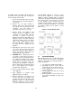
7.9.1 Parallel Piping the boiler outlet pipe. Therefore, the control requires a boiler outlet temperature sensor and a system temperature sensor In parallel piping applications, the boiler outlet temperature is typically the same as the system temperature. Therefore the operating temperature sensor is the boiler outlet sensor. Figure 8: Primary / Secondary Piping Figure 7: Parallel Piping 7.9.
Figure 10: Typical Low Water Temperature System Figure 11: Typical Instantaneous Water System 13
Figure 12: Typical Water Heating System Figure 13: Typical Water Heating System 14
8 INSTRUMENTATION AND CONTROLS 8.1 SAFETY CONTROLS The Boiler Temperature Controller (BTC 1) for this appliance is a Camus 78-0017 SmartFlame control. The BTC 1 uses a Liquid Crystal Display (LCD) as a method of displaying boiler information. The BTC 1 is used to setup and monitor the operation of the system. The BTC 1 uses three push buttons for selecting and adjusting settings. High Temperature Limit The high temperature limit is located behind the appliance’s access doors.
Figure 15: Boiler Temperature Control (BTC 1) 8.4 MODES OF OPERATION Mode 1: Constant Temperature Control This mode is designed for hydronic heating or domestic hot water (DHW). Once a heat demand is present, the BTC 1 turns on the appliance pump and modulates the boiler burner to maintain the boiler target at the boiler inlet sensor. A heat demand is generated when a 24VAC is applied across CD (common demand) and Ht D (heat demand).
Mode 2: Constant Temperature Control at System Sensor Mode 3: Dedicated Domestic Hot Water Operation This mode is designed for hydronic heating. Once a heat demand is present, the BTC 1 modulates the boiler burner to maintain the boiler target at the system sensor. A heat demand is generated when 24VAC is applied across CD (common demand) and Ht D (heat demand). Dem 1 on the LCD display is lit. This mode is designed for domestic hot water.
This mode is designed for hydronic heating. Once a heat demand is present, the BTC 1 turns on the appliance pump and modulates the boiler to maintain the calculated outdoor reset target at the boiler inlet sensor. Outdoor reset calculates the boiler target temperature based on the outdoor air temperature and reset ratio. Mode 5: Outdoor Reset using System Sensor This mode is designed for hydronic heating.
Mode 6: External Target Temperature using Boiler Inlet Sensor turns off the appliance and operates the boiler pump based on the PUMP DELAY setting. The auto re-set limit is set to 210°F and is fixed. In addition to the auto reset limit the factory installs a manual re-set limit set to 250°F. Figure 21: Mode 6 Piping Schematic The external input signal can be provided from a BMS, EMS or a tekmar tN4 System Control.
Mode 7: External Target Temperature using System Temperature Sensor Mode 8: External Direct Drive Operation This mode is designed only for hydronic heating operation. This mode allows for an external control to operate the boiler through an analog direct drive input signal provided by a boiler sequencing control, such as, the S12 Sequencer. When operating in this mode the external heat demand and DHW demand are disabled.
8.5 Mode 8 - External analogue 0-10VDC signal closes the stage contacts to initiate heater. Modulating output of the control follows the analog external input signal. Temperature is controlled remotely independently of local settings. Boiler max. setting remains functional. - Intermittent pumping provided Typical Factory Settings of Parameters for MicoFlame Grande BTC 1 (78-0017) This modulating MicoFlame is equipped with the Camus version of the Tekmar MPA control.
9 9.
9.2 MODE 1 & 2: SETPOINT OPERATION: VIEW DISPLAY From the Home display; 1) Press [ITEM] to view the following parameters: Display Parameter Name Boiler Target Temperature Parameter Description To provide a target setpoint for the heating system.
9.3 MODE 1 & 2: SETPOINT OPERATION: ADJUST DISPLAY From the Home display; 1) Press simultaneously to view the following parameters: Parameter Display Parameter Description Name Operating mode for the boiler. NOTE: A complete description of each mode can be found in section 8.4 Modes of Operation in this manual. Mode Parameter Range 1 to 8 Default = 1 o Boiler Target Temperature To provide a target setpoint for the heating system.
9.4 MODE 3: DEDICATED DOMESTIC HOT WATER OPERATION: VIEW DISPLAY From the Home display; 1) Press [ITEM] to view the following parameters: Display Parameter Name Parameter Description Parameter Range Boiler Target Temperature To provide a target setpoint for the heating system.
9.5 MODE 3: DEDICATED DOMESTIC HOT WATER OPERATION: ADJUST DISPLAY From the Home display; simultaneously to view the following parameters: 1) Press Display Parameter Name Parameter Range Parameter Description Operating mode for the boiler. NOTE: A complete description of each mode can be found in section 8.4 Modes of Operation in this manual.
9.6 MODE 4 & 5: OUTDOOR RESET OPERATION: VIEW DISPLAY From the Home display; 1) Press [ITEM] to view the following parameters: Display Parameter Name Parameter Description Outdoor Temperature Real-time Outdoor Temperature Boiler Target Temperature To provide a target setpoint for the heating system.
9.7 MODE 4 & 5: OUTDOOR RESET OPERATION: ADJUST DISPLAY From the Home display; 1) Press simultaneously to view the following parameters: Display Parameter Name Parameter Description Parameter Range Operating mode for the boiler. NOTE: A complete description of each mode can be found in section 8.4 Modes of Operation in this manual. Mode 1 to 8 Default = 1 o Outdoor Start Temperature Outdoor starting temperature used in the reset ratio for the heating system.
Display Parameter Name Parameter Range Parameter Description o Warm Weather Shutdown Temperature Warm weather shutdown temperature using outdoor reset. Temperature Units Select the desired unit of measurement 35 to 105 F, OFF o (2 to 41 C, OFF) Default = 0:20 min o o F, C o Default = F 9.
Display 9.9 Parameter Name Parameter Range Parameter Description Modulation Real-time modulating output percentage 0 to 100% Total Run Time Since Installation Monitors the amount of operational time since the MicoFlame was installed. The first two digits are the number of thousands of hours and the three digit display shows the number of hundreds of hours.
9.10 MODE 8: EXTERNAL DRIVE OPEATION: VIEW DISPLAY From the Home display; 2) Press [ITEM] to view the following parameters: Parameter Name Parameter Description Boiler Outlet Temperature Real-time Outlet Temperature to Boiler 14 to 266 F o (-10 to 130 C) Boiler Inlet Temperature Real-time Inlet Temperature to Boiler 14 to 266 F o (-10 to 130 C) Boiler Delta T Real-time temperature difference between the outlet sensor and the inlet sensor.
9.11 MODE 8: EXTERNAL DRIVE OPEATION: ADJUST DISPLAY From the Home display; simultaneously to view the following parameters: 1) Press Display Parameter Name Parameter Range Parameter Description Operating mode for the boiler. Mode Pump Delay NOTE: A complete description of each mode can be found in section 8.4 Modes of Operation in this manual. Boiler post pump time after burner has shut off, in seconds. 1 to 8 Default = 1 OFF, 0:20 to 9:55 min, On Default = 1:00 min o Temperature Units 9.
Error Message Description Inlet Sensor Short Circuit The boiler will continue operation. Test the inlet sensor and related wiring. The error message will clear once the error condition is corrected and a button is pressed. Inlet Sensor Open The boiler will continue operation Test the inlet sensor and related wiring. The error message will clear once the error condition is corrected and a button is pressed.
Error Message Description DHW Sensor Open The control will not operate the burner. Test the DHW sensor and related wiring. The error message will clear once the error condition is corrected and a button is pressed. Flame Proof Error Flame was not proved within 120 seconds of Demand 1 10 Pilot Flame Rectification Setting The pilot flame rectification was preset at the factory. The following description is for the benefit of the start-up technician should minor adjustment be required.
Air Flow Setting The fan inlet air shutter has been preset at the factory. The following description is for the benefit of the start-up technician should minor adjustment be required. Optimum results are obtained when the appliance is operated with air box pressure as set in Table 12.
Main Burner When all pilot flames are established, a flame rectification circuit is completed between the sensor and the burner ground. The flame sensing circuit in the ignition module detects the flame current, shuts off the spark generator and energizes the combination valve operator. Once all pilots are lit the main gas valve opens and matches gas input to the available air. As the fans ramp up gas input is adjusted accordingly.
Table 13 –Air Box Settings at Full Fire MODEL 2000 2500 3000 3500 4000 MODEL 2000 2500 3000 3500 4000 A qualified service technician should follow this procedure when burner needs cleaning. AIR BOX “ W.C. (with burner firing) Burner Burner Burner Burner #1 #2 #3 #4 1.9 1.9 (2.2) (2.2) 1.5 1.5 1.5 (1.8) (1.8) (1.8) 1.9 1.9 1.9 (2.2) (2.2) (2.2) 1.6 1.6 1.6 1.6 (1.9) (1.9) (1.9) (1.9) 1.9 1.9 1.9 1.9 (2.2) (2.2) (2.2) (2.2) FLUE SWITCH RECYCLE POINT “ W.C Burner Burner Burner Burner #1 #2 #3 #4 1.5 1.5 (1.
11.2 REMOVAL OF COMBUSTION CHAMBER LINING 11.3 PILOT BURNER Turn the pilot firing valve to off position and allow the appliance to try for ignition. Observe the spark making sure that it is strong and continuous. The combustion chamber insulation in this appliance contains ceramic fiber material. Ceramic fibers can be converted to cristobalite in very high temperature applications.
12 OPERATION AND SERVICE 12.1 PRE-START CHECKLIST Once satisfied replace the regulator adjustment screw cap and the elbow pressure tap plug. Table 15 – Gas pressures at inlet to pilot PROPANE Before operating the boiler, the entire system must be filled with water, purged of air and checked for leaks. Do not use Stop leak or other boiler compounds. The gas piping must also be leak tested. Minimum (inches W.C.) Maximum (inches W.C.) 3.9 9.3 NATURAL GAS 1.3 3.
The following description is for the benefit of the start-up technician should minor adjustment be required. Locate screw (2) labeled as and make adjustments as necessary to satisfy the combustion values in Table 16. The markings on the setting screws are labeled as “+” and “-“, for more and less gas, respectively. Turn the screw 1/4 turn in either way for each adjustment to keep track of the adjustments.
the level of water in the expansion tank should not exceed ¼ of the total volume with the balance filled with air. Start up appliance following instructions provided. Operate entire system including pumps and radiation for at least 1 hour. Check water level in expansion tank. If level exceeds ½ of tank volume, air is still trapped in system. Shut down appliance and continue to run pumps. Within 3 days of start up, recheck all air vents and expansion tank as described above. 12.
14 TROUBLE SHOOTING GUIDE SYMPTOM 1. Power light is not lit when switch is flipped to “ON” 2. Water flow light remains off. 3. Pilot sparks but does not light 4. Pilot lights momentarily, goes out and then sparks again repeatedly 5. Pilot lights but main burner does not fire. 6. Main burner lights but cycles off after a few minutes 7. Appliance starts to whine as the temperature rise increases. SOLUTION • Check wiring to switch. • Activate push button for latch relay if provided.
15 TYPICAL GAS TRAIN Figure 28 – Gas Train 43
16 ELECTRICAL DIAGRAMS 16.
17 EXPLODED VIEW & PARTS LIST MODULATING MICOFLAME GRANDE 45
MODULATING MICOFLAME GRANDE OUTDOOR AND/OR CONDENSING 46
MICOFLAME GRANDE REPLACEMENT PARTS LIST Ref # 1 2 3 4 5 6 7 8 9 10 11 12 13 14 15 16 17 18 Part Name Combustion Chamber End Panel - Left Combustion Chamber End Panel - Right Combustion Chamber Rear Panel Combustion Chamber Support - Left Combustion Chamber Support - Right Combustion Chamber Base Combustion Chamber Upper Front Flue Collector Top Flue Collector End Bracket Base Panel Outer Jacket Top Cover Outer Jacket Back Panel Outer Jacket Front Lower Panel Outer Jacket Front Upper Panel Base Support
Ref # 22 23 24 25 26 27 28 29 30 31 32 33 34 35 37 38 39 40 41 42 43 44 45 46 47 Part Name Outer Jacket Side Panel - Left Fan Mounting Support - Right Burner Door Stop Heat Exchanger Header Stop Bar Fan Mounting Support - Left Burner Door V Baffles HX Front and Back Baffles Outer Jacket Sight Glass Frame Outer Jacket Door Jam Heat Exchanger Support Weldment Inner Jacket Sight Glass Frame Outer Jacket Top Panel Support Control Panel Assembly Three Tiles Burner Box Assembly Economizer Cover* Economizer Assem
Ref # 51 52 53 54 55 56 Part Name Control Panel Outdoor Cover Door** Inlet Outlet Header Outdoor Cover** Gas Valve Actuator MicoGrande Modulating harness-2 burner main MicoGrande Modulating harness-3 burner MicoGrande Modulating-4 burner main MicoGrande Modulating harness-Water end harness, right MicoGrande Modulating harness-Water end harness 2burner, left MicoGrande Modulating harness-Water end harness 3-4 burner, left MicoGrande Modulating harness-Panel main (110V) MicoGrande Modulating harness-Pane
Valve * Condensing Models Only ** Outdoor Models Only Not Shown in Exploded View 50
WARRANTY GENERAL Camus Hydronics Limited (“Camus”), extends the following LIMITED WARRANTY to the owner of this appliance, provided that the product has been installed and operated in accordance with the Installation Manual provided with the equipment. Camus will furnish a replacement for, or at Camus option repair, any part that within the period specified below, shall fail in normal use and service at its original installation location due to any defect in workmanship, material or design.
52
CAMUS Hydronics is a manufacturer of replacement parts for most copper finned water heaters and heating boilers as well as a The CAMUS CERTIFIED! Seal assures you that Reliability, Efficiency & serviceability are built into every single unit! For more information supplier of specialty HVAC products. Our service line is open 24 hours, 7 days a week! on our innovative products from CAMUS Hydronics Limited, call 905-696-7800 today. CAMUS HYDRONICS LTD.