
Service manual


1
1 GENERAL INFORMATION
Camus Hydronics proudly introduces the
Modulating MicoFlame Grande series of water
heaters / hydronic boilers. The Modulating
MicoFlame Grande is a fan assisted appliance
based on a push through design which offers
several venting options. Heat output is controlled
by an adjustable ratio air/gas control valve. The
Modulating MicoFlame Grande models are
capable of modulating from 100% down to 40%
of rated input. These gas-burning appliances are
thoughtfully designed for easy operation and
maintenance. We are confident that you will
come to appreciate the benefits of our product.
The installation of this heater must conform to
the requirements of the authority having
jurisdiction or, in the absence of such
requirements, to the latest or current as
amended National Fuel Gas Code, ANSI Z223.1
or current CAN/CGA B149 Installation Codes.
All electrical wiring must be done in accordance
with the requirements of the authority having
jurisdiction or, in the absence of such
requirements, with the National Electrical Code,
ANSI/NFPA 70 or the Canadian Electrical Code
Part I, CSA C22.1 Electrical Code.
Vent installations must be in accordance with
Part 7, Venting of Equipment, of the latest or
current as amended National Fuel Gas Code,
ANSI Z223.1, or Section 7, Venting Systems
and Air Supply for Appliances, of the current
CAN/CGA B149, Installation Codes and
applicable provisions of the local building codes.
When required by the authority having
jurisdiction, the installation must conform to the
Standard for Controls and Safety Devices for
Automatically Fired Boilers, ANSI/ASME CSD-1.
The qualified installer shall instruct the end user
in the safe and correct operation of this
appliance and shall ensure that the heater is in
safe working order prior to leaving the job site.
WARRANTY
Factory warranty shall apply only when the
boiler is installed in accordance with local
plumbing and building codes, ordinances and
regulations, the printed instructions provided
with it and good industry practices.
Excessive water hardness causing a lime build-
up in the copper coils or tubes is not a fault of
the boiler. Consult the factory for
recommendations for use in hard water areas.
Damage to the heat exchanger as a result of
scaling or corrosive water conditions in non-
warrantable
Excessive pitting and erosion on the inside of the
copper tube may be caused by high water velocity
or the use of an undersized boiler for a DHW
application and is not covered by warranty.
Using or storing corrosive chemicals in the vicinity
of this boiler can rapidly attack the copper tubes
and voids warranty.
The primary heat exchanger of this boiler is
intended to operate under non-condensing
conditions. Inlet temperatures must be maintained
at 130
o
F (55
o
C) for non-condensing and
condensing appliances. Warranty is void if the
primary heat exchanger is allowed to operate in
condensing mode.
Damage caused by freezing or dry firing voids
warranty.
This boiler is not to be used for temporary heating
of buildings under construction.
2 LOCATION
Install this appliance in a clean, dry location with
adequate air supply and close to a good vent
connection.
Do not locate this appliance in an area where it will
be subject to freezing unless precautions are
taken.
The appliance is approved for installation directly
on combustible flooring and should be located
close to a floor drain in an area where leakage
from the appliance or connections will not result in
damage to the adjacent area or to lower floors in
the structure.
If necessary a suitable drain pan must be installed
under the appliance.
If the appliance is installed above the level of the
building’s radiation system, a low water cutoff
device must be installed in the appliance outlet at
the time of installation. Some local codes require
the installation of a low water cutoff on all systems.
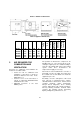
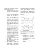
Table 1: Service Clearances
TOP: 24” REAR: 24”
SIDES: 24” FRONT: 48”
This appliance is suitable for alcove installation
with minimum clearances to combustibles as
follows:
Table 2: Clearance to Combustibles
TOP: 12”
SIDES:
12”
REAR: 12”
VENT: 6”
FLOOR:
0”